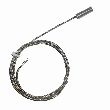
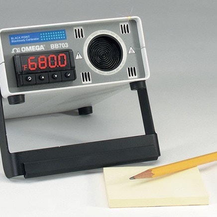
One of the easiest ways to measure and record temperature is with a thermocouple. Thermocouples perform reliably in most environments, tolerating temperature extremes, vibration and even ionizing radiation. However, they are susceptible to the effects of electromagnetic fields, so should be used with caution, or not at all, in such places.
This White Paper from Omega Engineering discusses the problems with using thermocouples in electromagnetic environments and makes recommendations for alternative types of temperature instrumentation. Individual sections address:
- Thermocouple theory and application
- Electromagnetic vulnerabilities
- Induced voltage
- Induction heating
- Common-mode voltage issues
- Alternative temperature measurement devices
Thermocouple Theory and Application
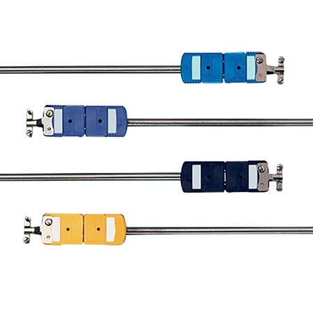 Thermocouples Probes with Connectors
Thermocouples make use of the Seebeck Effect, discovered by Thomas Johann Seebeck in 1821. This is the phenomenon whereby electrical current flows in a circuit made from dissimilar metals, when their two junctions are at different temperatures.
The metals used in a thermocouple must have thermoelectric properties. This is when the electrons are able to diffuse through the material. At higher temperatures the electrons gain kinetic energy, becoming more mobile and increasing the degree to which they move, so creating changes in electrical potential. Many nickel-based alloys have such characteristics and are used in most common thermocouple wires. For example, the Type K thermocouple uses junctions of Chromel and Alumel, both of which include significant proportions of nickel. Other material combinations used in thermocouples are based on platinum-rhodium and tungsten-rhenium, which also possess thermoelectric properties.
The current and voltage produced are proportional to the difference in temperature between the two junctions, although the relationship is not exactly linear. The actual voltages are very small. In a Type K thermocouple (widely used owing to its broad temperature range and low cost) the change is 41 mV per degree Celsius. Other thermocouple types produce changes of a similar magnitude. Consequently thermocouple signals must be amplified for use in measurement systems. Inevitably, any additional voltage in the signals due to external causes gets amplified at the same time.
Electromagnetic Vulnerabilities
High voltages are common in many situations where temperature measurements are needed, and electromagnetic fields are unavoidable. Induction heating is used throughout industry and temperature must be measured to ensure consistent processes. Electrical power lines carry high voltages. Transformers see high loads and can become very hot. Even spark plugs used in internal combustion engines (not only automobile engines but large generator sets) generate transient electromagnetic signals.
Electromagnetic fields affect thermocouple readings in two ways, they may:
- Induce voltage in the thermocouple wires
- Cause inductive heating of the thermocouple
Additionally, common-mode voltage relative to earth ground will add voltage to the thermocouple signal. These problems can occur in dc environments but are more severe in the presence of ac.
Induced Voltage
Faraday’s Law describes the phenomenon where moving an electrical conductor through a magnetic field results in the generation of electrical potential. The same effect can create voltage in thermocouple wires, especially if the wires are aligned perpendicular to a changing field. Given that the Seebeck effect produces very small voltages even a small field can alter the temperature reading.
Induction Heating
Subjecting a conductor to an alternating electromagnetic field creates eddies giving rise to heating. Thus with nickel being electrically conductive, an alternating magnetic field which might be found around a large motor or generator, will heat the temperature measurement device itself. This will result in a signal that does not accurately portray the temperature being measured.
Common-mode Voltage Issues
When a thermocouple is used alongside or as part of electrical equipment it is often connected to that supply. Once electrically energized it is possible for a difference between earth ground and equipment ground to affect the thermocouple signal voltage. The solution in such cases is to provide galvanic isolation of the temperature measurement system, or alternatively, to look at other temperature measurement methods.
Alternative Temperature Measurement Devices
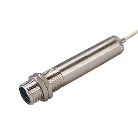 Infrared Temperature Sensor/Transmitter
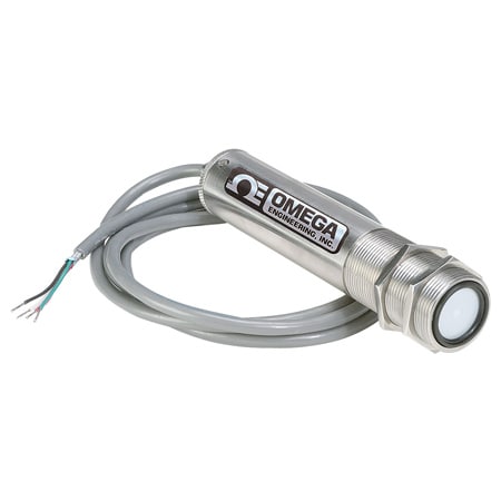 Infrared Temperature Sensor/Transmitter
Two technologies to explore are Pt100-type resistance temperature devices (RTDs) and the detection of infrared (IR) emission.
RTDs (where the measuring principle is the change in resistance of a length of platinum wire) are renowned for high accuracy and have good immunity to electromagnetic fields. However, they tend to be fragile and are not always suitable for industrial environments.
Measurement of IR emission has the advantage of being non-contact and can be performed at distances of several feet or more, depending on the size of the emitter. It takes advantage of Planck’s Law that describes how a body radiates energy in proportion to its temperature. One challenge to be addressed is that different surfaces at the same temperature will radiate at differing rates. Described as a difference in emissivity, this should be taken into account when measuring temperature with any kind of IR detector.
Omega Engineering offers several IR temperature sensors/ transmitters suitable for use in a wide range of industrial situations. The OS137A comes in a NEMA 4 rated 1" diameter stainless-steel housing and can be used at distances up to 48" (Note: the measurement target should fill the field of view of the sensor. If not, the measured temperature will not be accurate).
Three temperature ranges of OS137A are available covering temperatures up to 538°C (1000°F). A laser sighting accessory can be mounted to the front during set-up to ensure accurate alignment with the target. Output type must be specified when ordering: choose from voltage, current or Type K thermocouple outputs. Facility exists for an alarm set point and emissivity is adjustable.
At 3⁄4" diameter the OS136 is a more compact infrared sensor/ transmitter. Performance is similar to the OS137A although the viewing angle is wider (which may require closer placement). Unlike the OS137A, emissivity is fixed at 0.95, so corrections must be made for targets that are differing.
Takeaways
Thermocouples measure temperature in microvolts per degrees Celsius. These signals need amplification to be useful, which makes them susceptible to measurement errors when used in electromagnetic environments. Voltages can be induced in the thermocouple wires, induction heating can raise the temperature of the thermocouple, and grounding issues can increase the voltage measured.
While various filters and various shielding methods can be used another approach is to switch measurement technology. Both RTDs and IR emission detection have good tolerance to electromagnetic fields although RTDs are often though too fragile for industrial environments. IR sensor/transmitters provide non-contact measurement with a range of output options and are available in robust protective housings.
