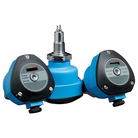
The FSW-6000/7000 Series are thermal flow switch monitors designed to monitor flow status and also used to detect level of liquids, air and gas. A chain of 8 LED’s gives the user a visual indication of the flow rate. In addition, there isalso a dichromatic LED, which shows the switch point status of the unit. The sensing element and connection of the FSW-6000/7000 Series are made with 316 SS. The standard enclosure is glass-filled nylon and is also available in an aluminum enclosure for hazardous environments. The FSW-6000/7000 Series can be made with a great variety of process connections such as threaded, flange, or sanitary.
The FSW-6000/7000 Series line of thermal flow switch monitors is based on the principle of thermal dispersion. A typical configuration uses two platinum Resistance Temperature Detectors (RTD’s) set within the tip of the sensor. One RTD is heated a few degrees above the temperature of the medium and the other RTD is used as a reference, sensing the actual process temperature. The second RTD also monitors the temperature of the medium, as any changes in temperature must be compensated for in the first RTD. As the process medium flows over the tip of the sensor it disperses some of theheat from the first RTD. The temperature change between the two RTD's signals the probe’s electronics and the switch changes state once the set point has reached.
The FSW-6000/7000 Series may be installed in a pipe or tank using the thread or connection provided. Use only the hexagon when tightening to achieve a seal, do not use the body. The body should be rotated after tightening to leave the cable gland in suitable orientation. The FSW-6000/7000 Series is not affected by its fixing position so it may be installed at any angle around the pipe. However, it is recommended that with horizontal pipe runs the sensor should be installed on the side, into the middle of the pipe. In vertical pipes, the FSW-6000/7000 Series should be installed when there is flow in an upward direction against gravity. Care should be taken when installing the sensor that the probe extends clear of the pipe’s internal wall and is fully immersed into the flow. In pipes with smaller diameters, some care should also be taken so that the sensor is not screwed too far into the line.
SPECIFICATIONS Accuracy: ±10% of setpoint Repeatability: ±1% of setpoint Power Supply: FSW-6000: 85 to 240 Vac (50/60 Hz) FSW-7000: 24 Vdc ±10% Temperature Range: Process: -20 to 80°C (-4 to 176°F) [sanitary option to 120°C (248°F) for CIP] Operating: -20 to 60°C (-4 to 140°F) Max Pressure: 300 bar (4351 psi) Protection Class: NEMA 4 (IP65) Wetted Materials: 316 SS Enclosure Material: Glass filled nylon standard or aluminum die cast option Process Connection: ½ to 1½ NPT, Tri-Grip™, or flange (others available, consult Flow Engineering Department) Output: 250 Vac SPDT 5 A relay Switch Point Adjustment: Potentiometer Bargraph: Green LED: Flow rate above setpoint Yellow LED: Flow is at above setpoint Red LED: Flow is below setpoint Switch Point Status: Red LED: No flow Green LED: Flow Response Time: 1 to 10 seconds Max Start up Delay: 12 seconds Switching Range: 3 cm/s to 3 m/s (0.09 to 9.84 ft/sec) (liquid), 5 cm/sec to 15 m/sec (0.16 to 49 ft/sec) (gas) Dimensions: Nylon Head: 88 Dia x 80 mm H (3.5 x 2.5' H) Aluminum Head: 88 Dia x 108 mm H (3.5 x 4.25') Insertion Length: 13⁄8, 2 and 3' standard, for other lengths consult Flow Engineering Maximum insertion Length is 36'