The SSR series is no longer available. Please see the SSRL series as a possible substitute or contact our sales department.
These SSR’s control resistance heaters up to 10 kW using solid state relays in conjunction with lower rated temperature controllers. Solid state relays are SPST, normally open switching devices with no moving parts, capable of millions of cycles of operation. By applying a control signal, an SSR switches “ON” the ac load current, just as the moving contacts do on a mechanical contactor. Three-phase loads can be controlled using 2 or 3 SSR’s. Use 3 SSR’s for “Y” or “star” 3-phase loads using a neutral line. Two SSR’s will control “delta” loads with no neutral line. Three solid state relays are also used when there is no neutral load to provide redundancy and extra assurance of control.
“Switching” takes place at the zero voltage crossover point of the alternating current cycle. Because of this, no appreciable electrical noise is generated, making SSR’s ideal for environments where there are apparatuses susceptible to RFI.
These SSR’s are of the twin SCR type, inherently more reliable and capable of higher overloads before failure than triacs. Heat is developed in a solid state relay due to the nominal voltage drop across the switching device. To dissipate the heat, an SSR must be mounted on a finned heat sink or aluminum plate. An SSR should be located where the ambient temperature is relatively low, since the current switching rating is lowered as the temperature increases. Another SSR characteristic is a small leakage current across the output when the relay is open. Because of this, a voltage will always exist on the load side of the device.
In comparing SSR’s with mechanical contactors, the SSR has a cycle life many times that of a comparably priced contactor. However, SSR’s are more prone to failure due to overload and improper initial wiring. Solid state relays can fail, contact closed, on overload circuits.
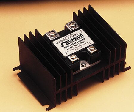
Finned heat sinks are anodized fabrications that come complete with tapped mounting holes and screws. See thermal rating curves and ordering instructions for proper selection.
SSR baseplate to heat sink thermal resistance is affected by use of a thermally conducting compound. OMEGATHERM™ OT-201 placed between the heat sink and SSR baseplate will significantly improve the thermal conductivity. It is also suggested that 10-inch-pounds of torque be used on the SSR mounting screws.