FLR1000 Series flow sensors can measure extremely low flow rates from 20 mL/min to 500 L/min. These sensors are suitable for a wide variety of industrial, commercial, and laboratory flow applications.
Not for use with Hydrogen or Helium. FLR1000 Series flow sensors operate on 12 Vdc power and are designed for incorporation into data acquisition systems that supply 12.5 Vdc to sensors and receive 0 to 5 Vdc linear signals in return. Because of their cost effectiveness, FLR1000 Series units may replace conventional glass tube and ball flow meters in applications in which an electrical signal proportional to flow rate is desired.
The FLR1000 Series uses a Pelton-type turbine wheel to determine the flow rate of the gas. The rotation rate of the turbine wheel is linear over a wide dynamic range. The electro-optical system consists of a diode emitting energy in the infrared spectrum. Light energy is alternatively reflected and absorbed from "spokes" deposited on the small turbine wheel. This reflected light energy is detected by a photodiode. Thus, as the turbine wheel rotates in response to gas flow rate, electrical pulses are generated. Processing circuitry provides a DC voltage output proportional to the flow rate. For example, output signal is 1.0 Vdc at 20% of rated flow, 2.5 Vdc at 50% of rated flow, 4.0 Vdc at 80% of rated flow, and 5.0 Vdc at 100% of rated flow. Sensors can handle 20% above their rated flow without being damaged.
SPECIFICATIONS FLR1000 Series Accuracy: ±3% FS
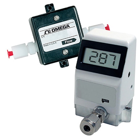
Display: 3½-digit LCD, 22 mm (7/8") H
Output Signal: 0 to 5 Vdc, adjustable ±20% (typical)
Power Requirement: 11.5 to 15 Vdc regulated, 30 mA (typical)
Standard Sensor Material: 40% glass filled polyphenelene sulfide, glass window, stainless steel bearing support; sapphire shaft and bearing; FKM rubber O-rings standard
Pressure Rating: 40 psi at 20°C (68°F) for gas, 100 psi for liquid, 500 psi for brass units using liquid services
Temperature Rating: 0 to 50°C (32 to 122°F)
Temperature Sensitivity: ±0.2%/°C
Linearity: ±3% FS
Repeatability: ±0.5% FS from 50 to 100% of rated max flow for gas; ±0.2% FS for liquid
Cable Assembly: 0.9 m (3') cable length
Dimensions: Display: 76 x 44 x 89 mm (3 x 1.75 x 3.5")
Non-Display: 60 x 42 x 37 mm (2.35 x 1.65 x 1.25")
Pressure Sensitivity: ±0.07%/mm Hg (using air at 1 to 3 atm)
Mounting: Holes for #4 screw provided
Voltage Output Models: 11.5 to 12.5 Vdc (0.4 W @ 12 Vdc)
Current Output Models: 18 to 24 Vdc (1.2 W @ 24 Vdc), 50 mA
| Gas Flow Models - PPS Construction |
Model No.
No Display | Model No.
with Display | Flow Range | Max Pressure Drop | Acetal Tube Fitting |
| FLR1001 | FLR1001-D | 20 to 100 mL/min | 20 Inches Water | 1/8" |
| FLR1002 | FLR1002-D | 40 to 200 mL/min | 8 Inches Water | 1/8" |
| FLR1003 | FLR1003-D | 100 to 500 mL/min | 2 Inches Water | 1/8" |
| FLR1004 | FLR1004-D | 200 to 1000 mL/min | 2 Inches Water | 1/8" |
| FLR1005 | FLR1005-D | 0.4 to 2 L/min | 2 Inches Water | 1/4" |
| FLR1006 | FLR1006-D | 1.0 to 5 L/min | 2 Inches Water | 1/4" |
| FLR1201 | FLR1201-D | 2.0 to 10 L/min | 3 Inches Water | 1/4" |
| FLR1202 | FLR1202-D | 4.0 to 20 L/min | 3 Inches Water | 3/8" |
| FLR1203 | FLR1203-D | 10 to 50 L/min | 3 Inches Water | 3/8" |
| FLR1204 | FLR1204-D | 20 to 100 L/min | 3 Inches Water | 1/2" |
| FLR1205 | FLR1205-D | 40 to 200 L/min | 5 Inches Water | 1/2" |
| FLR1206 | FLR1206-D | 100 to 500 L/min | 20 Inches Water | 1/2" |
| Liquid Flow Models - PPS Construction |
Model No.
No Display | Model No.
with Display | Flow Range | Max Pressure Drop | Acetal Tube Fitting |
| FLR1007 | FLR1007-D | 13 to 100 mL/min | 10 psi | 1/8" |
| FLR1008 | FLR1008-D | 20 to 200 mL/min | 10 psi | 1/4" |
| FLR1009 | FLR1009-D | 50 to 500 mL/min | 10 psi | 1/4" |
| FLR1010 | FLR1010-D | 100 to 1000 mL/min | 6 psi | 1/4" |
| FLR1011 | FLR1011-D | 0.2 to 2 L/min | 6 psi | 1/4" |
| FLR1012 | FLR1012-D | 0.5 to 5 L/min | 6 psi | 3/8" |
| FLR1013 | FLR1013-D | 1.0 to 10 L/min | 10 psi | 3/8" |