Call us at 1-888-826-6342

1/8 DIN Economical Multisignal panel meter for Process, Temperature and Electrical measurements
Economical multisignal digital panel meter in 1/8 DIN size for panel mount, and a wide range of applications. Accepts AC and DC voltage signals from mV up to 600 V and currents up to 5 A (AC measures in True RMS), process signals (mA and Vdc) with excitation voltage included, thermocouples K, J, E, N, L, R, S, B, T and C, resistive temperature probes (Pt100, Pt500, Pt1000, Ni100, Ni200, Ni1000, PTC and NTC), resistances, potentiometers and frequency. Scalable reading with 4 digits up to 9999 / -1999 with configurable decimal point. Two independent alarms, configurable as maximum or minimum, with hysteresis and setpoint.
Optional 1 or 2 relay outputs, 4/20 mA isolated analog output, and Modbus RTU isolated serial communications.
Front protection IP65. Connections with plug-in screw terminals.
Instrument designed for industrial use, highly flexible, allows for integration in multiple applications, reduced cost, excellent quality and optional customization available.
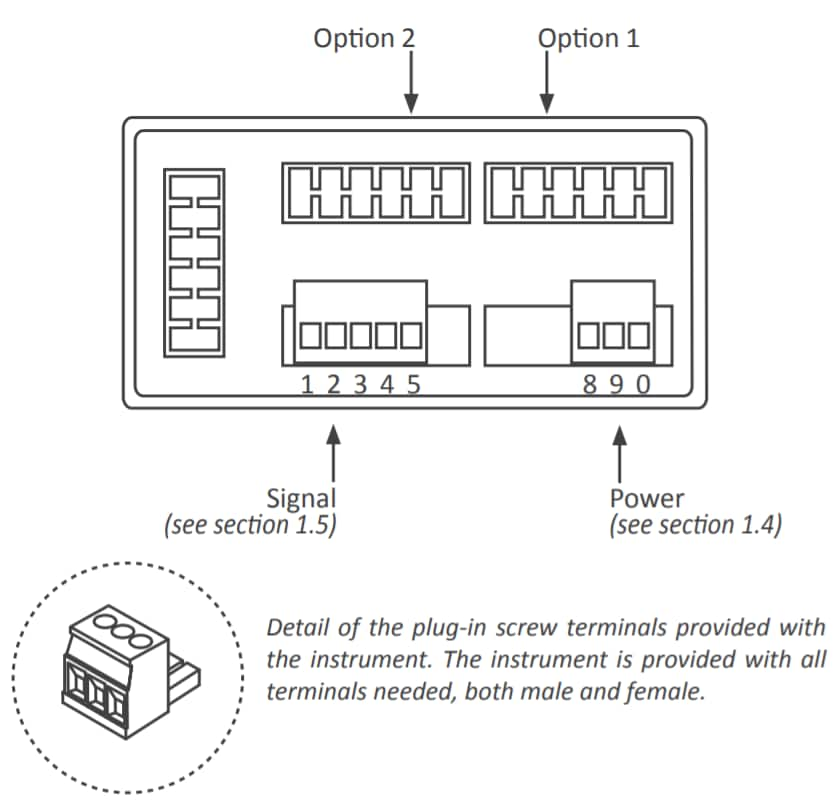
Earth connection - The instrument does not need earth connection for correct operation nor for compliance with security regulations. Terminal 9 is not connected to any internal circuit and is provided only as a safe place for earth wire.
Fuse - As requested by security regulation 61010-1, add a protection
fuse to the power to act as disconnection element, easily accessible
to the operator and identified as a protection device.
250 mA time-lag for power voltage > 50 Vac/dc
400 mA time-lag for power voltage < 50 Vac/dc
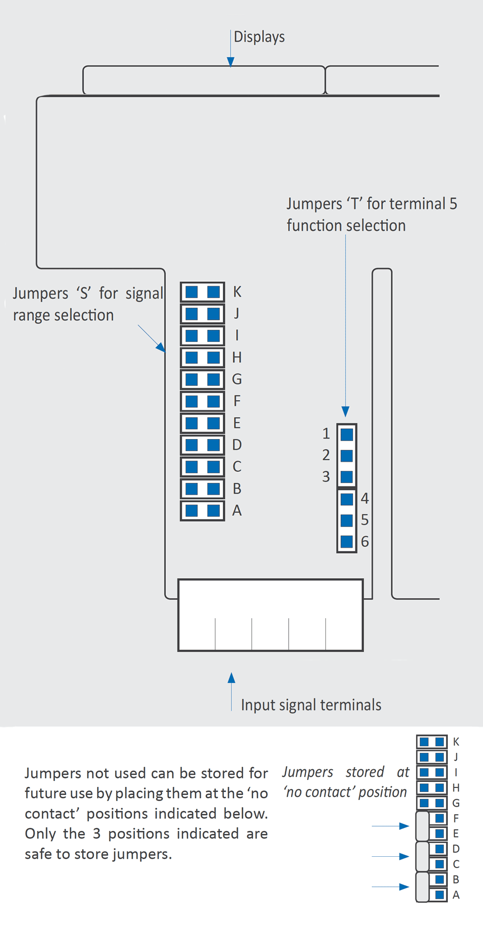
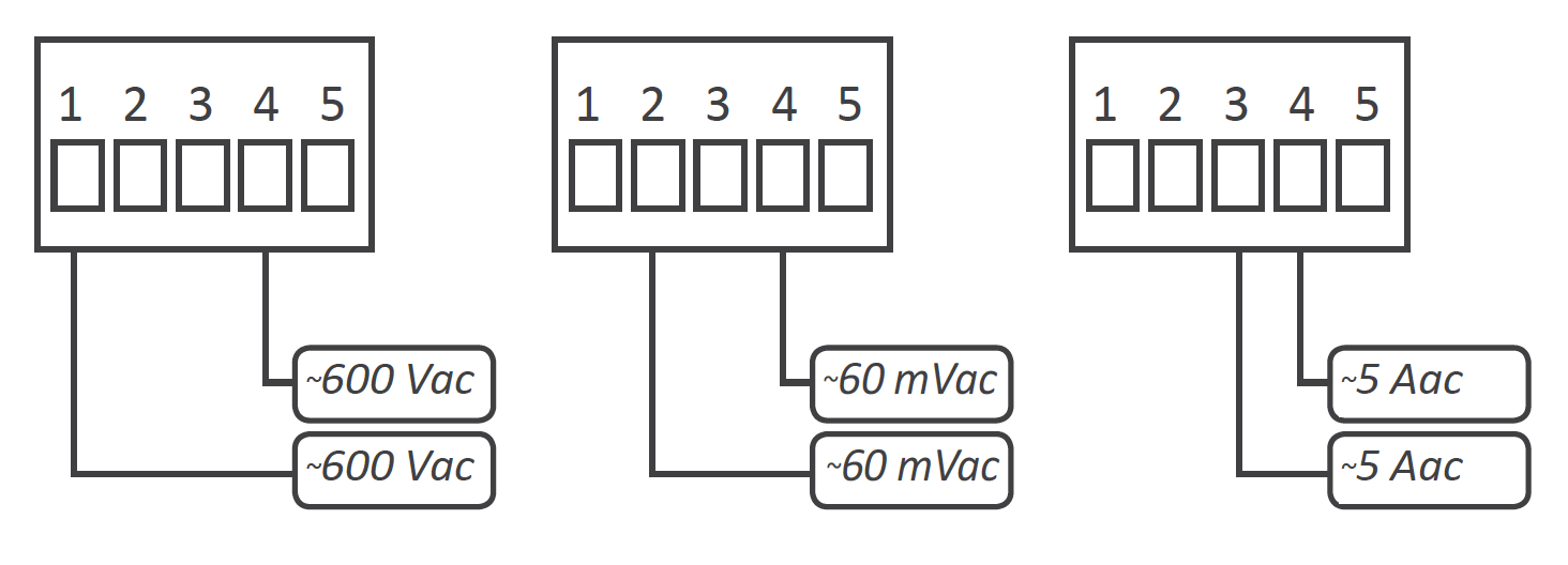
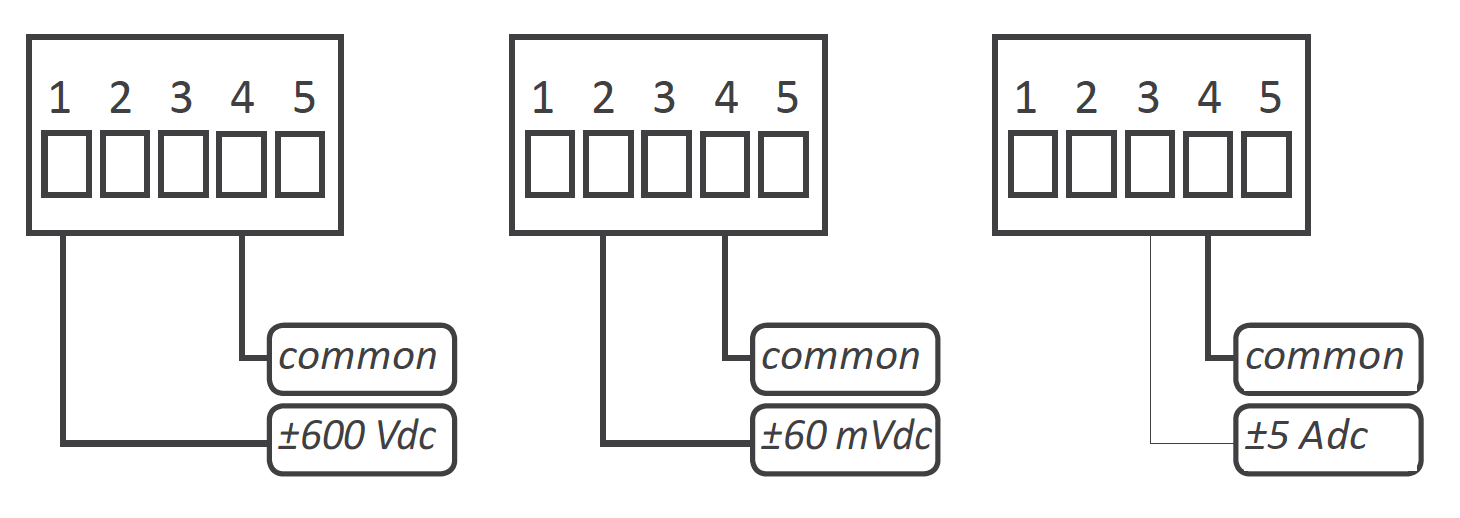
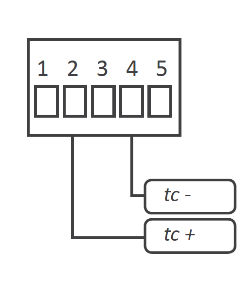
Signals up to 600 V and 200 V (AC and DC) must be connected at terminals 1 and 4. Signals for 5 A current (AC and DC) must be connected at terminals 3 and 4. All other signals must be connected between terminals 2 and 4. Terminal 5 is a 'multifunction' terminal, configurable with one of the following functions:

| Digits | |
|---|---|
| number of digits | 4 |
| led | 7 segments led |
| color | red |
| height | 14mm |
| Reading | |
|---|---|
| max. reading | 9999 |
| min. reading | -1999 |
| decimal point | configurable X.X.X.X |
| readings | 3 readings / second |
| display refresh | 3 refresh / second |
| step response | 300 mSec. (0 % to 99 % signal) |
| overrange | reading flashes at '9999' |
| underrange | reading flashes at '-1999' |
| Accepted input signal | |
|---|---|
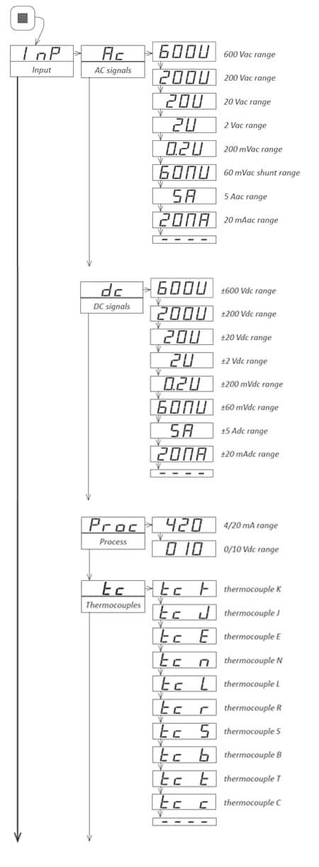
| AC voltages and currents | 600 Vac, 200 Vac, 20 Vac, 2 Vac 200 mVac, 60 mVac, 5 Aac, 20 mAac (see section 1.10) |
| DC voltages and currents | ±600 Vdc, ±200 Vdc, ±20 Vdc, ±2 Vdc ±200 mVdc, ±60 mVdc, ±5 Adc, ±20 mAdc (see section 1.11) |
| thermocouples | K, J, E, N, L, R, S, B, T y C (see section 1.12) |
| temperature 'Pt' | Pt100 (2 and 3 wires with automatic compensation up to 30 R), Pt500, Pt1000 (see section 1.13) |
| temperature 'Ni' | Ni100, Ni200, Ni1000 (see section 1.13) |
| temperature 'NTC' | (see section 1.14) |
| temperature 'PTC' | (see section 1.15) |
| process | 4/20 mA, 0/10 Vdc (active and passive) (see section 1.16) |
| Measuring Frequency | frequency up to 100 Hz (see section 1.17) |
| resistances | ranges of 5 K and 50 K (see section 1.18) |
| potentiometers | nominal value 500 Ohm up to 20 KOhm (see section 1.18) |
| Accuracy at 25ºC Thermal drift | see following sections for each signal 150 ppm/º |
| Excitation voltage | +15 Vdc (max. 30 mA) for process signals +5 Vdc for potentiometers (at terminal 5, see sections 1.5 and 1.16) |
| Power supply | |
|---|---|
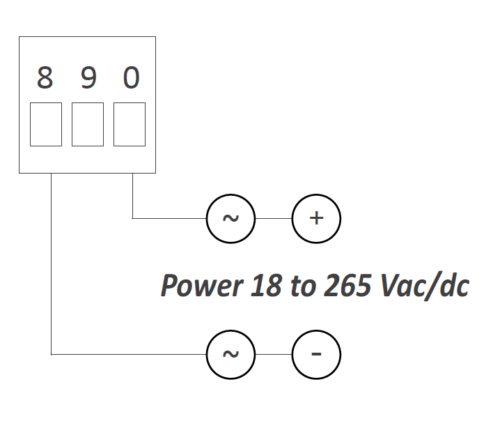
| power 'U' isolation | 18 to 265 Vac/dc 1500 Veff. isolation tested for 60 sec. |
| consumption (without 'Eco') | <1.5 W meter only <2.5 W meter with options |
| consumption (with 'Eco') | <0.3 W meter only <1.5 W meter with options |
| Functions included | Section | |
|---|---|---|
| Fast access | to alarm setpoints, maximum and minimum | 1.20 |
| External Control | second scaling decimal point 0, 1, 2 or 3 'hold' reading 'tare' function memory of maximal memory of minimum | 1.24 |
| 'ECO' mode | reduced consumption | 1.23 |
| Alarms | setpoint hysteresis set as max or min type | 1.29.3 |
| Offset reading | add a fixed number of counts to reading | 1.22 |
| Display filter | recursive 'steps' | 1.29.7 |
| Simplified scaling | 1.21 | |
| Memory | max and min memory | 1.29.4 |
| Password | blocks configuration | 1.29.7 |
| Display brightness | 5 levels | 1.29.7 |
| Table 1 - Functions included | ||
| Configuration | 3 front push buttons |
| Front protection | IP65, NEMA13 |
| Output options | relay, analog, serial (see section 2) |
| Mechanical | |
| mounting | panel |
| connections | plug-in screw termnials |
| housing material | ABS, polycarbonate (V0) |
| weight | <150 grams |
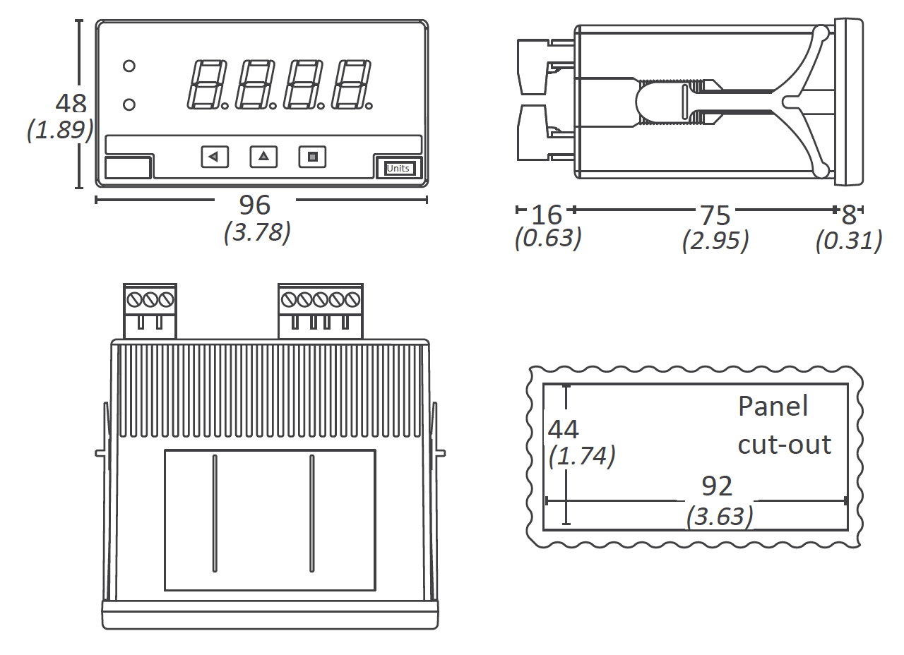
| front size | 96 x 48 mm (1/8 DIN) |
| panel cut-out | 92 x 44 mm |
| deep | 91 mm (including terminals) |
| Temperature | |
| operation | from 0 to +50ºC (32 to 122ºF) |
| storage | from -20 to +70ºC (-4 to 150ºF) |
| 'warm-up' time | 15 minutes |
Internal jumpers 'S' are associated to the signal range. The position of internal jumper 'T' assigns the function of the multifunction terminal 5. At 'T'ble 2' see a list of signal ranges and associated jumper 'S' and 'T'. At Table 3 see the position for jumper 'T' associated to each function of the multifunction terminal 5. To access the internal jumpers, open the housing as explained at section 1.26. For additional information on each signal range see the following sections:
| Range | Jumpers 'S' | Jumper 'T' |
|---|---|---|
| AC voltages and currents | ||
| ~600 Vac | G I | 4-5 |
| ~200 Vac | I | |
| ~20 Vac | A I | |
| ~2 Vac | B I | |
| ~200 mVac | C I | |
| ~60 mVac | E I | |
| ~5 Aac | I | |
| ~20 Vac | D I | |
| DC voltages and currents | ||
| ±600 Vdc | G | 4-5 |
| ±200 Vdc | --- | |
| ±20 Vdc | A | |
| ±2 Vdc | B | |
| ±200 mVdc | C | |
| ±60 mVdc | E | |
| ±5 Adc | --- | |
| ±20 mAdc | D | |
| Process | ||
| 4/20 mA | D | 1-2* |
| 0/10 Vdc | A | |
| * jumper 1-2 to activate Vexc. Select 4-5 to activate function 'EK' | ||
| Resistances | ||
| 0 to 5 K | F H K | 4-5 |
| 0 to 50 K | F K | |
| Thermocouples | ||
| Tc.K | E | 4.5 |
| Tc.J | ||
| Tc.E | ||
| Tc.N | ||
| Tc.L | ||
| Tc.R | E J | |
| Tc.S | ||
| Tc.T | ||
| Tc.C | E | |
| Tc.B | E J | |
| Pt and Ni probes | ||
| Pt100 (3 wire) | F H J | 5-6 |
| Pt100 (2 wire) | F H | 4-5 |
| Pt500 | F | |
| Pt1000 | F | |
| Ni100 | F H | |
| Ni200 | F H | |
| Ni1000 | F | |
| NTC probes | ||
| NTC | F K | 4-5 |
| PTC probes | ||
| KTY 121 | F | 4-5 |
| KTY 210, 220 | F H K | |
| Potentiometers | ||
| 0/100% | A | 2-3 |
| Table 2 - Jumpers 'S' and 'T' and signal ranges | ||
| Jumpers 'T' | Active function at terminal 5 | |
|---|---|---|
| 1 2 | Vexc (excitation voltage +15 Vdc) for process | |
| 2 3 | Potentiometer excitation (+5 Vdc) | |
| 4 5 | External control ('EK' function) | |
| 5 6 | Pt100 third wire | |
| Table 3 - Jumpers 'T' and function at multifunction terminal 5 | ||
| Vac ranges (Veff.) | Scale by default | Scalable | Jumper 'S' (see section 1.9) |
Jumper 'T' (see section 1.9) |
Accuracy (% FS) |
Max. oversignal | Connection (terminals) |
Zin |
|---|---|---|---|---|---|---|---|---|
| ~600 Vac | 600 | from 9999 to -1999 | G I | 4-5 | <0.30% (up to 150 Hz) |
800 Vac | 1(~) 4(~) | 12 M |
| ~200 Vac | 200.0 | I | 800 Vac | 12 M | ||||
| ~20 Vac | 20.0 | A I | 150 Vac | 2(~) 4(~) | 1 M | |||
| ~2 Vac | 2.000 | B I | 100 Vac | 100 K | ||||
| ~200 mVac | 200.0 | C I | 30 Vac | 10 K | ||||
| ~60 mVac | 60.0 | E I | 3 Vac | 1 M | ||||
| Table 4 - Measuring ranges in Vac | ||||||||
| Aac ranges (Veff.) |
Scale by default | Scalable | Jumper 'S' (see section 1.9) |
Jumper 'T' (see section 1.9) |
Accuracy (% FS) |
Max. oversignal | Connection (terminals) |
Zin |
|---|---|---|---|---|---|---|---|---|
| ~5 Aac | 5.00 | from 9999 to -1999 | I | 4-5 | <0.50% (up to 150 Hz) |
7 Aac (max. 7sec.) | 3(~) 4(~) | 20 mOhm |
| ~20 mAac | 20.00 | D I | 25 mAac | 2(~) 4(~) | 4.7 R | |||
| Table 5 - Measuring ranges in Aac | ||||||||
See below a list of typical connections:
| Applications | ||
|---|---|---|
| ... with shunts ... | measure of AC currents through a current shunt of 60 mV, 100 mV or 150 mV and scaled reading | |
| ... with X/5, X/1 current transformers ... | measure of AC currents through a X/5 or X/1 current transformer and scaled reading | |
| ... direct measure ... | direct measure of currents up to 5 Aac | |
| ... with power line voltages ... | measure of voltages over power lines phase and neutral, of 230 Vac, 115 Vac, ... | |
| ... with power voltages ... | measure of phase to phase lines on power lines 380 Vac, 230 Vac, ... | |
| ... with AC voltages | measure of AC voltages in panels using 24 Vac, 48 Vac, ... | |
| Table 6 - Applications with measure of AC signals | ||
| Vdc ranges | Scale by default | Scalable | Jumper 'S' (see section 1.9) |
Jumper 'T' (see section 1.9) |
Accuracy (% FS) |
Max. oversignal | Connection (terminals) |
Zin |
|---|---|---|---|---|---|---|---|---|
| ±600 Vac | 600 | from 9999 to -1999 | G | 4-5 | <0.20% | 800 Vdc | 1(+) 4(-) | 12 M |
| ±200 Vdc | 200.0 | --- | 800 Vdc | 12 M | ||||
| ±20 Vdc | 20.00 | A | 150 Vdc | 2(+) 4(-) | 1 M | |||
| ±2 Vdc | 2.000 | B | 100 Vdc | 100 K | ||||
| ±200 mVdc | 200.0 | C | 30 Vdc | 10 K | ||||
| ±60 mVdc | 60.0 | E | <0.25% | 3 Vdc | 1 M | |||
| Table 7 - Measuring ranges in Vdc | ||||||||
| Adc ranges (Veff.) |
Scale by default | Scalable | Jumper 'S' (see section 1.9) |
Jumper 'T' (see section 1.9) |
Accuracy (% FS) |
Max. oversignal | Connection (terminals) |
Zin |
|---|---|---|---|---|---|---|---|---|
| ±5 Adc | ±5.00 | from 9999 to -1999 | --- | 4-5 | <0.25% | 7 Adc (max. 7sec.) | 3(+) 4(-) | 20 mOhm |
| ±20 mAdc | ±20.00 | D | <0.15% | 25 mAdc | 2(+) 4(-) | 4.7 R | ||
| Table 8 - Measuring ranges in Adc | ||||||||
See below a list of typical connections:
| Applications | ||
|---|---|---|
| ... with shunts ... | measure of DC currents through a current shunt of 60 mV, 100 mV or 150 mV and scaled reading | |
| ... direct measure ... | direct measure of currents up to 5 Adc and voltages up to 400 Vdc | |
| ... with batteries ... | measure of the battery voltage at 12 Vdc and 24 Vdc | |
| ... with tachometric dynamos ... | read the speed in RPM from a tachometric dynamo voltage signal | |
| ... with speed variators ... | measure the voltage signal from the variator, proportional to the RPM speed of the motor | |
| Table 9 - Applications with DC Signals | ||
See below connections for thermocouple:
| Thermocouple | Jumper 'S' (see section 1.9) |
Jumper 'T' (see section 1.9) |
Range in ºC (in ºF) |
Connection (terminals) |
Total error (cold junction included) |
|---|---|---|---|---|---|
| Thermocouple K | E | 4-5 | -100 / 1350ºC (-148 / 2462ºF) |
2(tc +) 4(tc -) |
<3º |
| Thermocouple J | -100 / 1200ºC (-148 / 2192ºF) |
||||
| Thermocouple E | -100 / 1000ºC (-148 / 1832ºF) |
||||
| Thermocouple N | -100 / 1300ºC (-148 / 2372ºF) |
||||
| Thermocouple L | -100 / 900ºC (-148 / 1652ºF) |
||||
| Thermocouple R | E J | 0 / 1768ºC (32 / 3214ºF) |
|||
| Thermocouple S | 0 / 1768ºC (32 / 3214ºF) |
||||
| Thermocouple T | -100 / 400ºC (-148 / 752ºF) |
||||
| Thermocouple C | E | 0 / 2300ºC (32 / 4172ºF) |
<5º | ||
| Thermocouple B | E J | 700 / 1820ºC (1292 / 3308ºF) |
|||
| Table 10 - Temperature ranges for thermocouples | |||||
See below a list of typical connections:
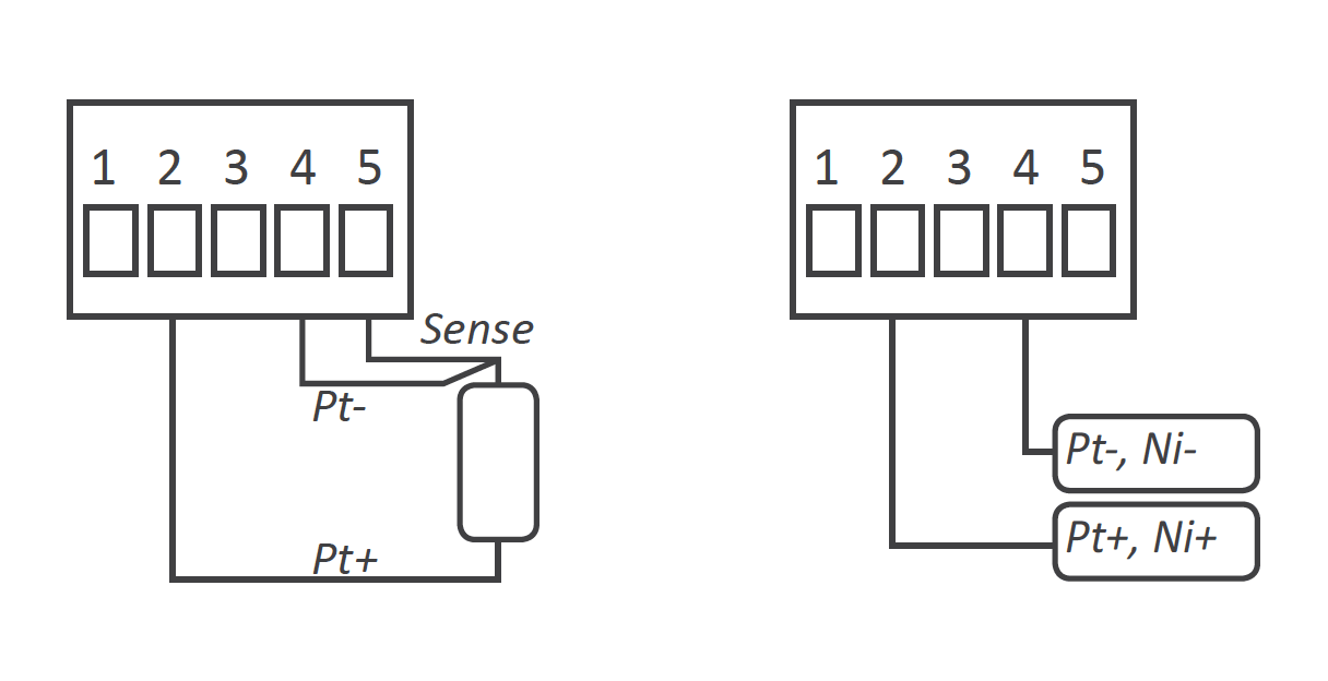
| Sensor | Jumper 'S' (see section 1.9) |
Jumper 'T' (see section 1.9) |
Range in ºC (in ºF) |
Total error | Connection (terminals) |
Current at sensor |
|---|---|---|---|---|---|---|
| Pt100 3 wires | F H J | 5-6 | -200 / 700ºC (-328 / 1292ºF) |
<1º | 2 (Pt+) 4 (Pt-) 5 (sense) |
<900 uA |
| Pt100 2 wires | F H | 4-5 | -200 / 700ºC (-328 / 1292ºF) |
2 (Pt+, Ni+) 4 (Pt-, Ni-) |
||
| Pt500 | F | -150 / 630ºC (-238 / 1166ºF) |
< 90 uA | |||
| Pt1000 | F | -190 / 630ºC (-310 / 1166ºF) |
< 90 uA | |||
| Ni100 | F H | -60 / 180ºC (-76 / 356ºF) |
< 900 uA | |||
| Ni200 | F H | -60 / 120ºC (-76 / 248ºF) |
< 900 uA | |||
| Ni1000 | F | -60 / 180ºC (-76 / 356ºF) |
< 90 uA | |||
| Table 11 - Ranges of temperature for Pt and Ni probes | ||||||
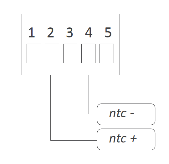
See below connections for NTC probe:
| Range of Measure | NTC probe | ||
|---|---|---|---|
| Temp. | R25 | Beta | |
| 100R | |||
| 1 MOhm | |||
| Table 12 - Data from NTC datasheet | |||
| NTC 'R25' (configurable)* |
Jumper 'S' (see section 1.9) |
Jumper 'T' (see section 1.9) |
Range of measure | Accuracy (% of reading) |
Connection (terminals) |
Beta (configurable) |
|---|---|---|---|---|---|---|
| 10K | F K | 4-5 | From -60ºC to 150ºC |
<1.5% of reading | 2 (NTC +) 4 (NTC -) |
3500 |
| Table 13 - *'Beta' is configurable from 2000 to 5500. 'R25' is configurable from 1.0 K up to 200.0 K. | ||||||
See below connections for PTC probe:
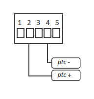
| Family | Sensor | Jumper 'S' (see section 1.9) |
Jumper 'T' (see section 1.9) |
Range in ºC (in ºF) |
Total Error |
|---|---|---|---|---|---|
| KTY 121 | KTY81-121 KTY82-121 |
F | 4-5 | -55 / 150ºC (-67 / 302ºF) |
<1º |
| KTY 210 | KTY81-210 KTY82-210 |
FHK | |||
| KTY 220 | KTY81-220 KTY82-220 |
FHK | |||
| Table 14 - Ranges of temperature for PTC probes | |||||
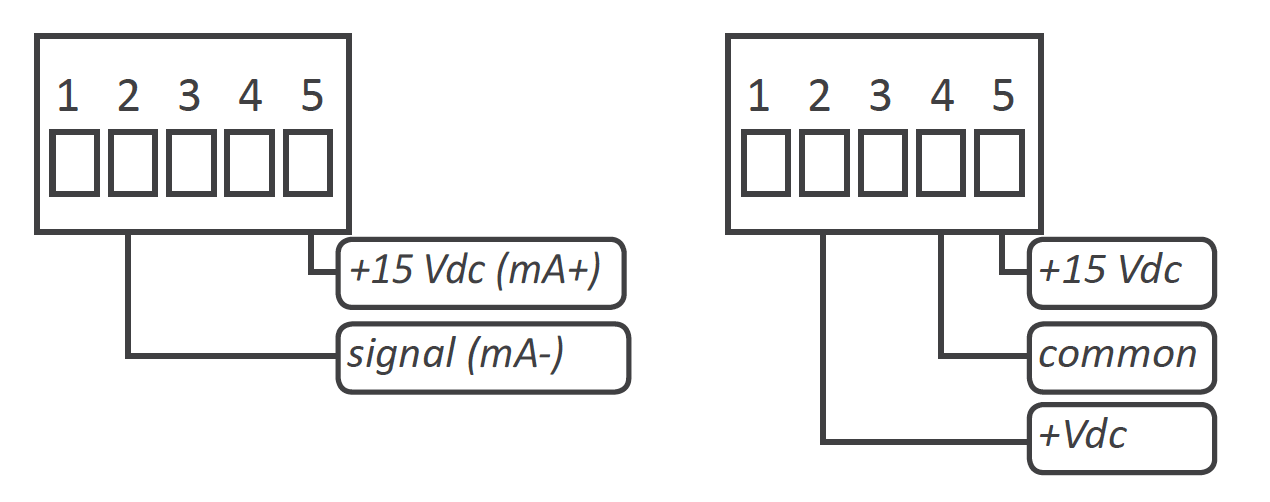
| Ranges of Measure | Scale by default | Scalable | Jumper 'S' (see section 1.9) |
Jumper 'T' (see section 1.9) |
Accuracy (%FS) | Max. oversignal | Connection (terminals) | Zin | |
|---|---|---|---|---|---|---|---|---|---|
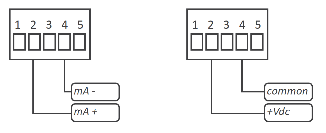
| 4/20 mA | passive (needs Vexc.) | 0/100.0 | de 9999 a - 1999 | D | 1-2 | <0.15% | 25 mA | 2 (signal) 5 (Vexc) | 4.7 Ohm |
| active | 4-5 | 2 (mA+) 4 (mA-) | |||||||
| 0/10 Vdc | passive (needs Vexc.) | A | 1-2 | <0.20% | 25 Vdc | 2 (+Vdc) 4 (comm.) 5 (Vexc) | 1 M | ||
| active | 4-5 | 2 (+Vdc) 4 (comm.) | |||||||
| Table 15 - Ranges of measure for process signals | |||||||||
| Ranges of measure | Scale by default | Scalable | AC Signal (see section 1.9) |
Jumper 'T' | Response time | Accuracy (% reading) |
|---|---|---|---|---|---|---|
| 15 to 100Hz | 0/100.0 | from 9999 to -1999 | select Vac or Aac range | 4-5 | 70mSec. | <0.15% of reading |
| Table 16 - Ranges of measure for frequency | ||||||
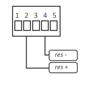
| Ranges of measure | Scale by default | Scalable | Jumper 'S' (see section 1.9) |
Jumper 'T' (see section 1.9) |
Accuracy (% of reading) |
|---|---|---|---|---|---|
| 0 to 5 K | 5.000 | from 9999 to -1999 | F H K | 4-5 | <1.5% of reading |
| 0 to 5 K | 50.00 | F K | |||
| Table 15 - Ranges of measure for resistances | |||||
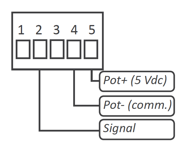
| Nominal pot. value | Ranges of measure | Scale by default | Scalable | Jumper 'S' (see section 1.9) |
Jumper 'T' (see section 1.9) |
Accuracy (% FS) |
|---|---|---|---|---|---|---|
| from 500 R up to 20 K | 0 to 100 % | 0/100.0 | from 9999 to -1999 | A | 2-3 | <0.5% |
| Table 16 - Ranges of measure for potentiometers | ||||||
The 'fast access' menu allows to configure the front key 'UP' ('5') as a direct access to the alarm 1 and / or alarm 2 setpoint values, and / or the memory of maximum and minimum reading. The objective is to provide the operator with a fast and direct access to alarm setpoints, without accessing the standard configuration menu.
Access to 'fast access' menu is still allowed even with active 'password' function, allowing the operator to modify the alarm setpoints, while still blocking any other change on the configuration.
The 'fast access' menu is configurable, and it allows to assign to the front key none, one, several or all of the available functions. In case of configuring access only to alarm 1, when pushing front key 'UP' ('5'), the display directly access the setpoint value of alarm 1 (same for alarm 2)
To configure the 'fast access' menu see section 1.29.4.
The instrument can scale the reading to any value between 9999 and -1999 and configure the decimal point position, for all signal ranges except temperature ranges (thermocouples, Ni and Pt sensors, NTC and PTC sensors) are not scalable. The scaling configuration is a simplified two steps process:
Some examples are explained below:
To configure the scaling see section 1.29.2.
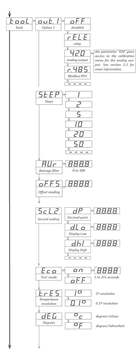
The 'Offset reading' ('oFFS') parameter allows a number of counts to be added to the reading. This is specially useful to manually compensate for resistance errors due to wire resistance, when measuring with 2 wires Ni and Pt probes, and resistances. Applies to all signal ranges. See configuration menu at 'Tools' \ 'oFFS' (see section 1.29.7).
The 'Eco' mode reduces the consumption of the instrument to a level of 0.3 W. The 'Eco' mode turns off the display, while the right decimal point remains flashing gently on and off, showing that the instrument is running on the background.
Display will turn on when an alarm activates, or when the operator touches any of the front keys. If no alarms are active, and there is no interaction from the operator, the instrument will turn off the display. The waiting time before display turn off is configurable from 5 to 255 seconds.
To configure the 'Eco' mode see the configuration menu at 'Tools' \ 'Eco' (see section 1.29.7).
The 'external control' function allows to activate, by closing a free potential contact, one of the following configurable functions:
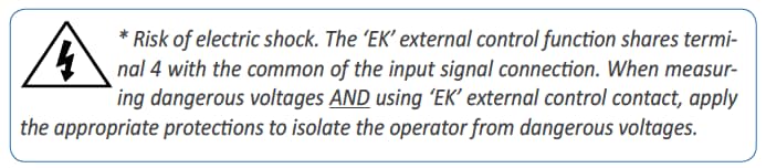
To configure the 'EK' external contact function, set internal jumper 'T' at position 4-5 (see section 1.9). The 'EK' external control function is not compatible with function 'Vexc' (excitation voltage), the measure of 3 wire Pt100, and the measure of potentiometers.
To assign a function to the 'external control' see the configuration menu at 'External control' (see section 1.29.6).
The function associated to the 'EK' external control activates when short-circuiting terminal 5 and terminal 4.
The instrument provides a 'second scaling', independent and additional to the standard scaling explained at section 1.21. Control of the scaling to be applied, with a free potential contact called 'External control'. To configure the 'second scaling' :
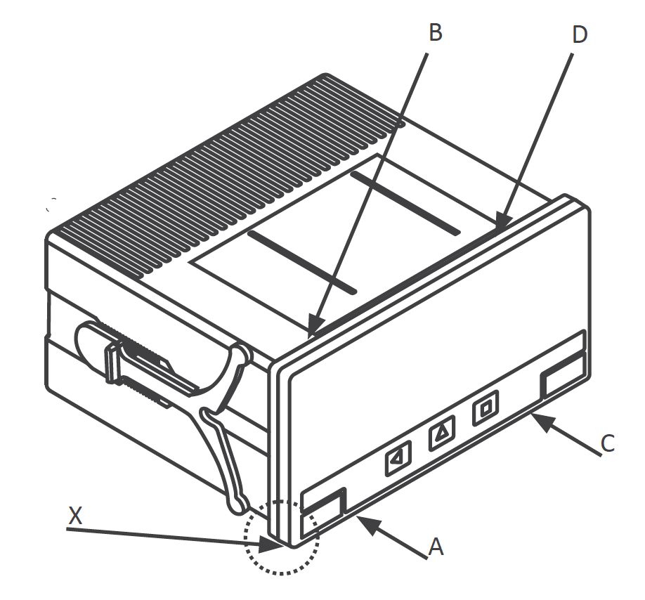
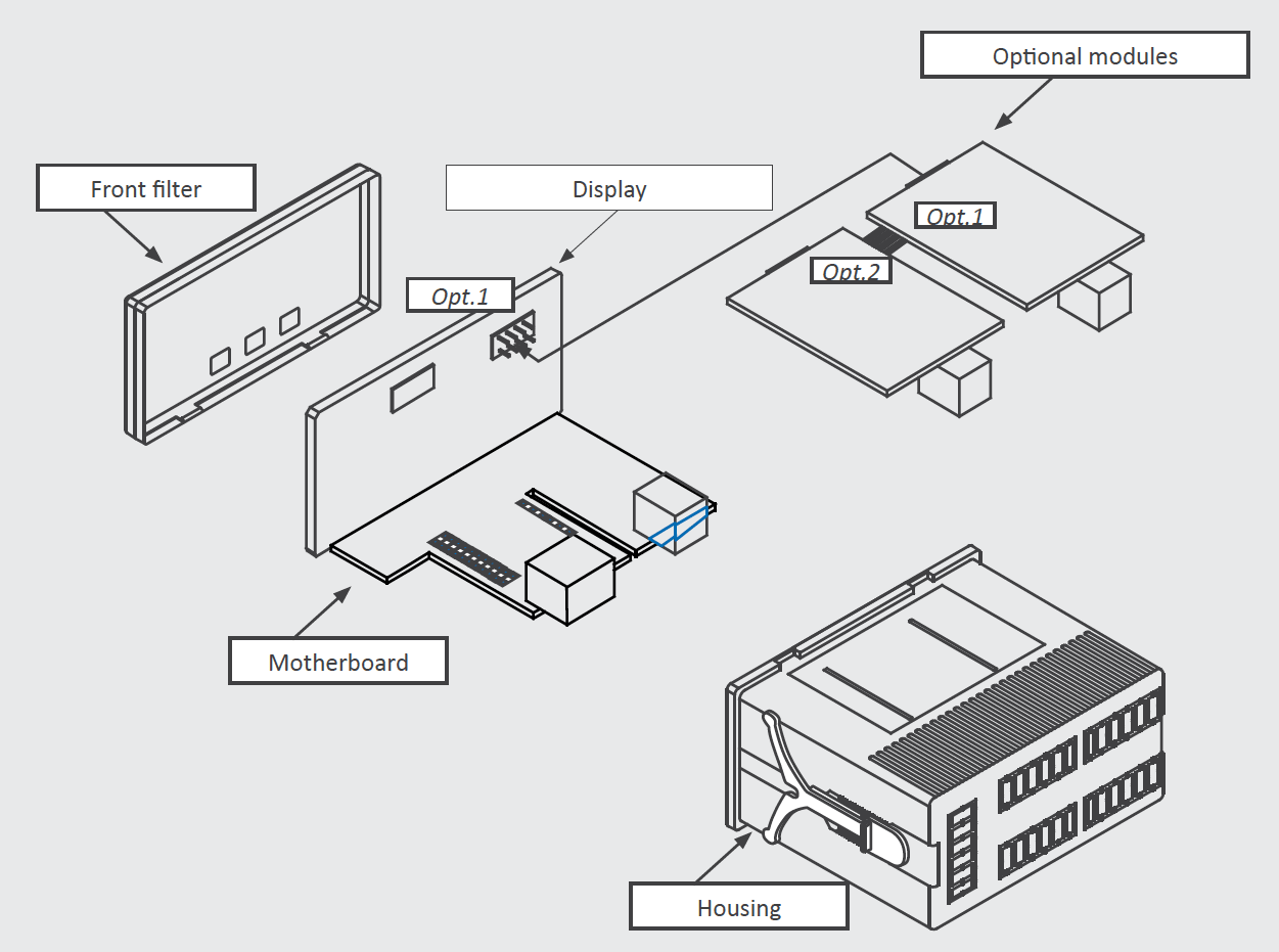
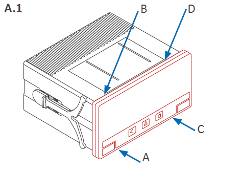
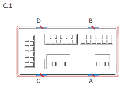
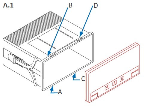
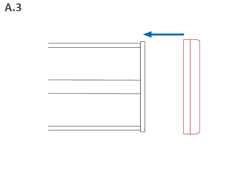
To open the housing and access the internal circuits, use a flat screwdriver to unlock clips 'D', 'C', 'B' and 'A', in this order. Remove the front filter. Let the inside of the instrument slide out of the housing.
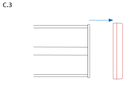
To reinsert the instrument make sure that all modules are correctly connected to the pins on the display module. Place all the set into the housing, assuring that the modules correctly fit into the internal guiding slides of the housing. Once introduced, place again the front filter at cover 'X', and then insert clips 'A', 'B', 'C' and 'D', in this order.
See section 3 for a detailed description on how to open and close the housing.
The instrument has two menus accessible to the user:
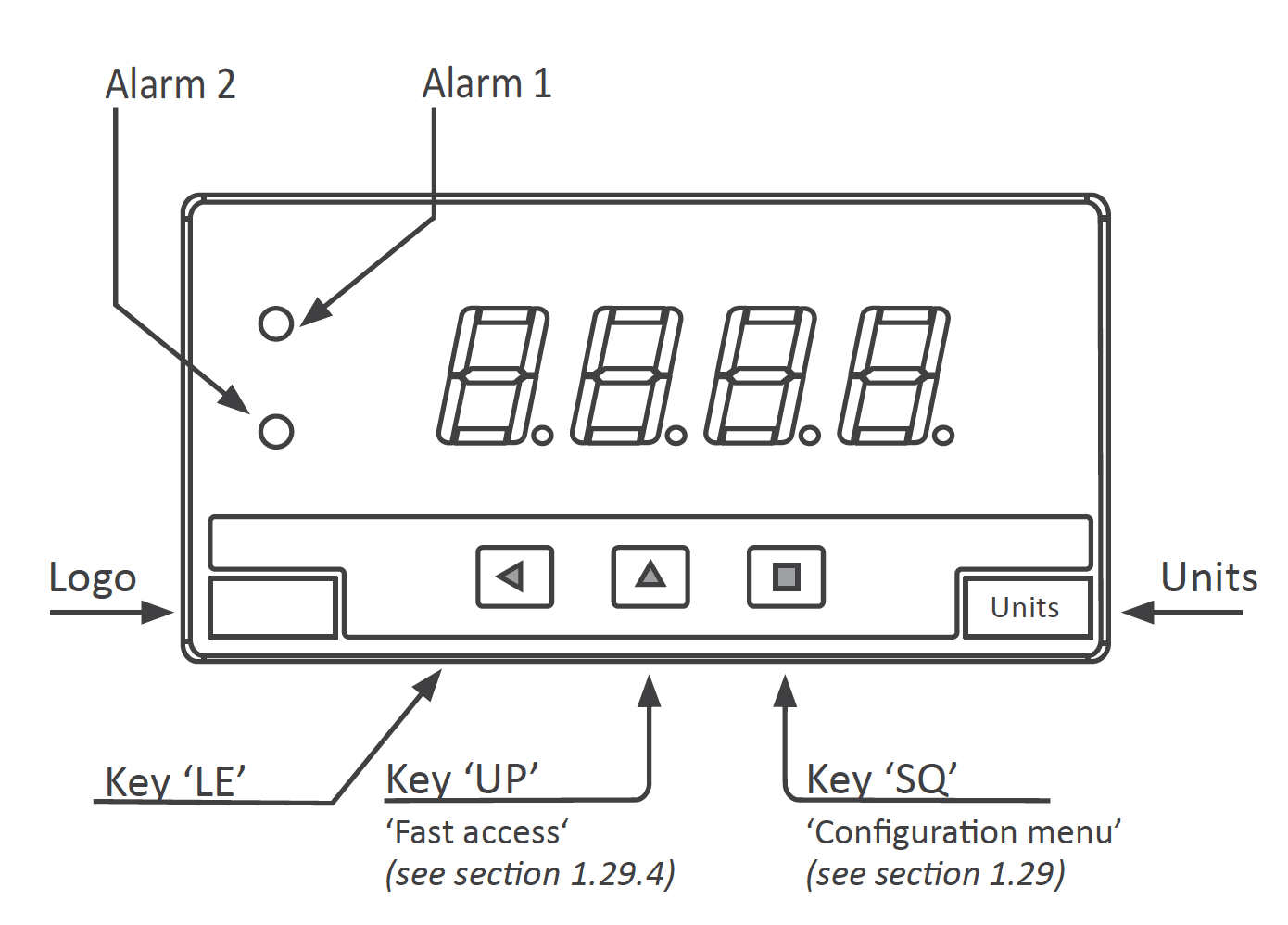
'Configuration menu' (key SQ) (■)
'Fast access' menu (key UP) (▲)
Configuration menu
The 'configuration menu' modifies the configuration parameters to adapt the instrument to the application needs. To access the 'configuration menu' press for 1 second the SQ (<) key. This access can be blocked by activating the 'Password' ('PASS') function. While operating the 'configuration menu', the alarm status is 'hold' to the status they had before accessing the menu, and the output and control modules remain in 'error' state. When leaving the 'configuration menu', the instrument applies a system reset, followed by a brief disconnection of the alarms and the output and control modules. Functionality is then recovered.
For a detailed explanation on the 'configuration menu' see section 1.30, and for a full view of the 'configuration menu' structure see section 1.30.
'Fast access' menu
The 'fast access' menu is an operator configurable menu, providing fast and direct access to the most usual functions of the instrument with a single key pad stroke. Press key UP (5) to access this menu.
See section 1.20 for a list of functions eligible for 'fast access' in this instrument. The 'Password' ('PASS') function does not block access to this menu. Accessing and modifying parameters in the 'fast access' menu does not interfere with the normal functionality of the instrument, and it does not generate any system reset when validating the changes.
Front key pad description
Key SQ (<) - press the SQ (<) key for 1 second to access the 'configuration menu'. Inside the menu, the SQ (<) key functions as a 'ENTER' key. It selects and accesses the menu option currently displayed. At menus with numerical value entries, it validates the number displayed.
Key UP (5) - the UP (5) key gives access to the 'fast access' menu. Inside the menus, it moves vertically through the different menu options. At menus with numerical value entries, it modifies the digit selected by increasing its value to 0, 1, 2, 3, 4, 5, 6, 7, 8, 9.
Key LE (3) - inside the menus, the LE (3) key functions as the 'ESCAPE' key. It leaves the selected menu, and eventually, will leave the whole menu. When leaving the 'configuration menu' with the LE (3) key, the changed parameters are activated. At menus with numerical value entries, the LE (3) key allows to select the active digit. To modify the value of the selected digit use the UP (5) key.
Menu 'rollback'
After 30 seconds without interaction from the operator, the instrument will rollback and leave the 'configuration menu' or the 'fast access' menu. All changes will be discarded.
Example of operation inside the 'configuration menu'.
The error messages are shown on display in flash mode.
| Messages and errors |
|---|
| 'h.udr' Hardware underrange ('h.udr') / overrange ('h.ovr'). 'h.oVr' Input signal is lower / higher than the minimum / maximum signal the instrument can detect. |
| 'd.udr' display underrange ('d.udr') / overrange ('d.ovr'). The 'd.oVr' instrument already displays the minimum / maximum value possible (9999 / -1999). |
| 'Err.0'* at the 'scaling' ('ScAL') menu entry, the defined slope is higher than '5000' (slope almost vertical). Entered values are dismissed and default values are activated. |
| 'Err.1' incorrect password. |
| Table 17 - Messages and error codes |
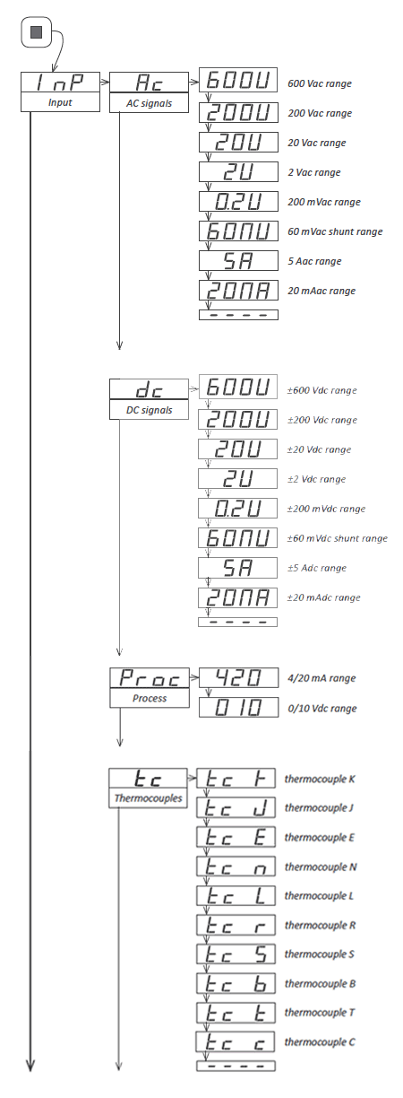
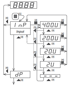
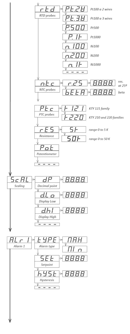
1.29.1 Input signal ranges
Access the 'Input' ('InP') menu to select the input signal range. For a correct reading, the internal jumper 'T' (see section 1.9) must also be selected accordingly.
The instrument offers the following signal ranges :
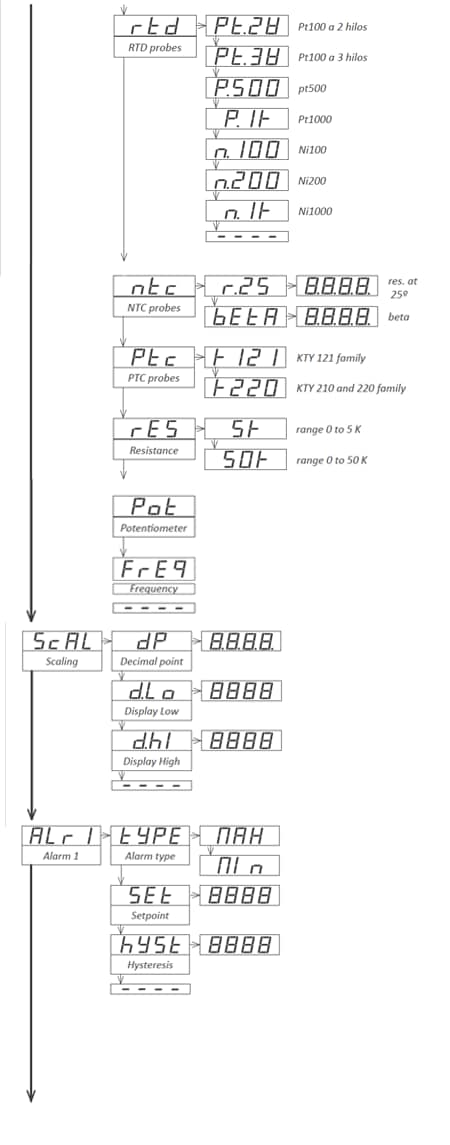
1.29.2 Scaling
Scale the reading at the 'Scaling' ('ScAL') menu. Temperature ranges (thermocouples, Pt and Ni probes, NTC and PTC probes) have direct temperature indication and are not scalable.
To configure the scaling, enter the 'Decimal point' ('dP') parameter and select the desired position for the decimal point, using key 'LE' (3).
Then configure at the 'Display Low' ('d.Lo') parameter the reading value associated to the low signal range and configure at the 'Display High' ('d.Hi') parameter the reading value for the high signal range. For more information see section 1.21.
1.29.3 Alarms
The instrument has 2 independent and configurable alarms.
Control the independent activation of relays A1 installed (optionally) at slots 1 and 2 (see section 2.1) from menu entries 'Alarm 1' ('ALr1') and 'Alarm 2' ('ALr2'). Alarms control also the activation of front leds '1' and '2' located as indicated at section 1.2.
To configure the alarms, enter at the alarm menu ('ALr1', or 'ALr2') and configure the following parameters:
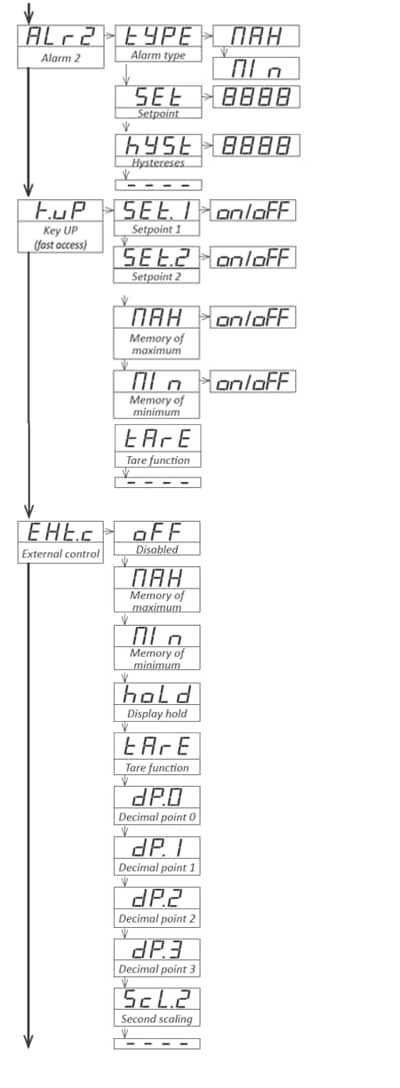
1.29.4 Fast access
The key 'UP' (5) at the front of the instrument gives access to a list of functions configurable by the operator. See section 1.27 for an explanation on how to operate the 'fast access' menu.
The 'Key UP (Fast access)' ('K.uP') menu allows user to select which functions will be accessible when pressing the front key 'UP' (5). Select 'on' to activate each function.
1.29.5 Super fast access
If only a single function is selected for the 'fast access' menu, pressing the the 'UP' (5) key will shortly display the function name and then automatically jump to the function value.
1.29.6 External control
An external on / off control can be connected to the rear of the instrument. The operator can then control the activation of a configured function based on the state of this control. Function remains activated while the external contact is closed, and will deactivate when contact is open. To configure the function associated to the external control, enter the menu 'External control' ('EXt.c').
Parameters 'Memory of maximum' ('MAX'), 'Memory of minimum' ('Min') and 'Display hold' ('hoLd') show on display a value which is not the actual measured input signal, therefore the values for this parameters will be shown in flash mode, indicating that the actual value is not the actual input value.
Parameters 'Decimal point 0' ('dP.0')and similar 'dP.1'and>, 'dP.2' and 'dP.3' control which decimal point is on. When the external contact closes, the decimal point selected lights on and the decimal point that was activated before will power off. When the external contact opens, the previous decimal point powers on again while removing the new decimal point. Display does not show in flash mode when decimal point functions are activated.
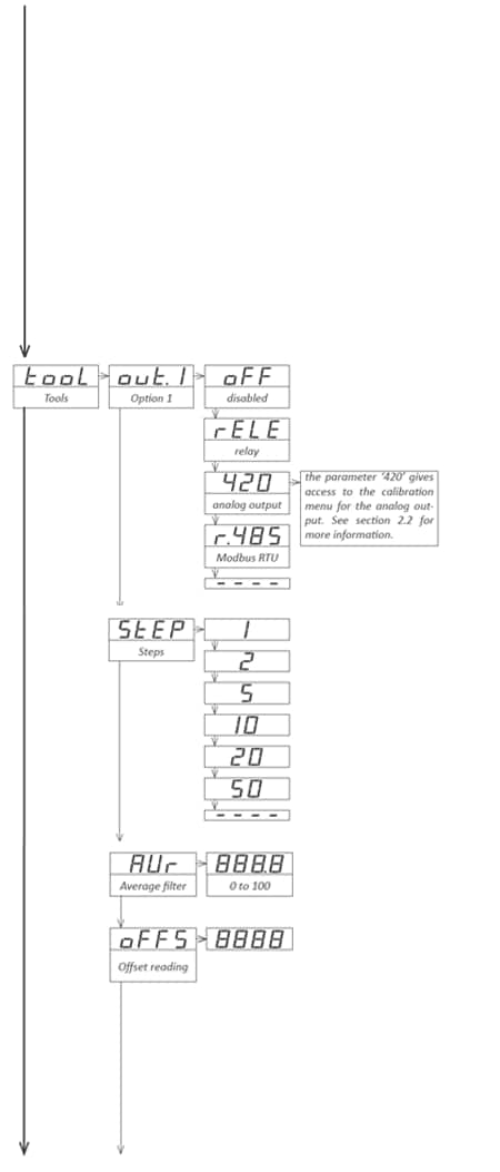
1.29.7 Menu 'Tools'
The 'Tools' ('tooL') menu contains multiple configuration options of the instrument.
Note : the parameter '420' gives access to the calibration menu for the analog output module. See section 2.2 for more information about this menu and the calibration.


This instrument has been designed and verified conforming to the 61010-1 CE Security Regulation, for industrial applications. Installation of this instrument must be performed by qualified personnel only. This manual contains the appropriate information for the installation. Using the instrument in ways not specified by the manufacturer may lead to a reduction of the specified protection level. Disconnect the instrument from power before starting any maintenance and / or installation action.
The instrument does not have a general switch and will start operation as soon as power is connected. The instrument does not have protection fuse, the fuse must be added during installation.
The instrument is designed to be panel mounted. An appropriate ventilation of the instrument must be assured. Do not expose the instrument to excess of humidity. Maintain clean by using a humid rag and do NOT use abrasive products such as alcohols, solvents, etc. General recommendations for electrical installations apply, and for proper functionality we recommend : if possible, install the instrument far from electrical noise or magnetic field generators such as power relays, electrical motors, speed variators, ... If possible, do not install along the same conduits power cables (power, motor controllers, electrovalves, ...) together with signal and/or control cables. Before proceeding to the power connection, verify that the voltage level available matches the power levels indicated in the label on the instrument. In case of fire, disconnect the instrument from the power line, fire alarm according to local rules, disconnect the air conditioning, attack fire with carbonic snow, never with water.

| Range | 600 Vac |
| Scaling and decimal point | 0/600 Vac = 0/600 |
| Alarms 1 | |
| Type | alarm as maximum |
| Setpoint | 1000 |
| Hysteresis | 0 counts |
| External control | off |
| Fast access | all off |
| Tools | |
| Option.1 | off (retains last configuration value) |
| Step | 1 |
| Average | 0 |
| Offset reading | 0 |
| Second scaling | 0/600 |
| ‘Eco’ mode | off |
| Temperature resolution | 1º |
| Degrees | ºC |
| Alpha | 385 |
| cJc | on |
| AC deadband | 20 |
| Brightness | 3 |
| Password | off |
| Option 1 configuration | |
| Option analog output | 0/100.0=4/20 mA |
| Option serial Modbus RTU | 9600 bps, address 1, format 8n1 |
| Jumpers ‘S’ | selected for 600 Vac |
| Jumper ‘T’ | selected for ‘EK’ external control function |
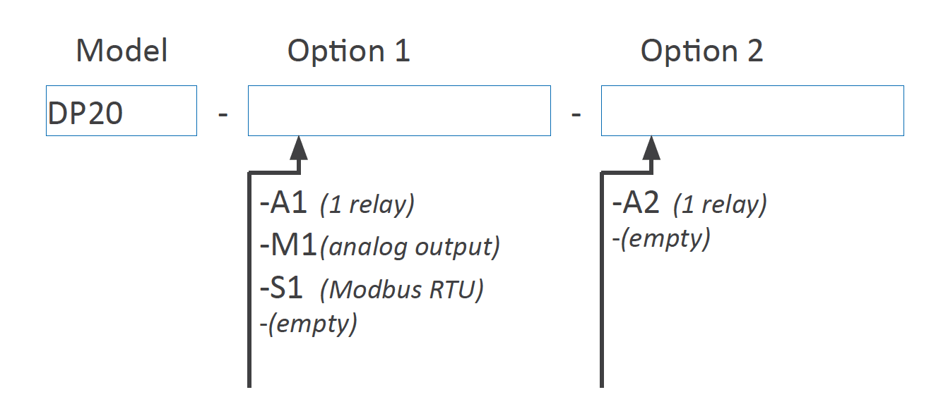
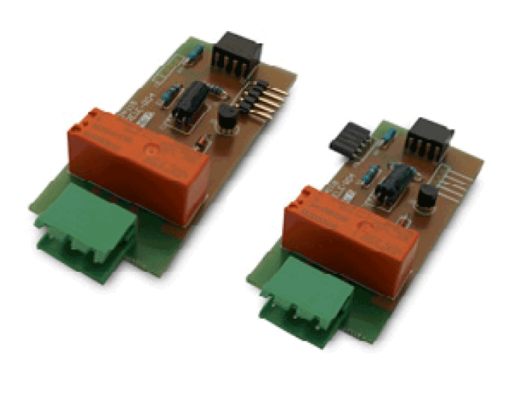
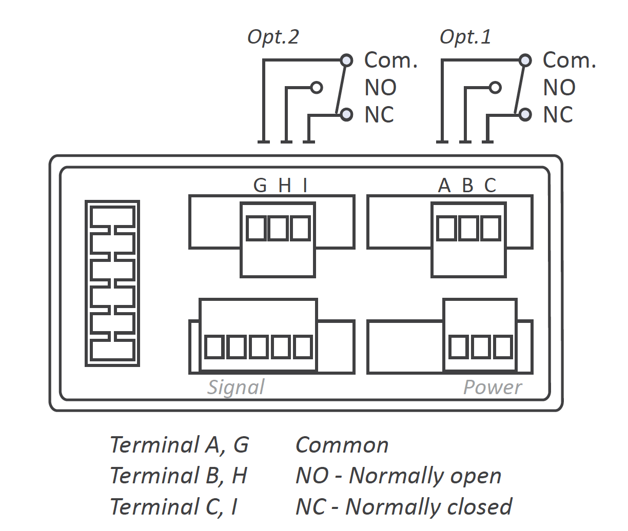
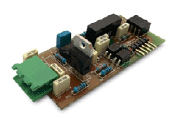
The A1 (and A2) modules offer 1 relay output to be installed at slot Opt.1 (module A2 at Opt.2). The relay installed at Opt.1 is controlled by alarm 1, and is configured from the ‘Alarm 1’ (‘Alr1’) menu explained at section 1.29.3. The relay installed at Opt.2 is controlled by alarm 2, and is configured from the ‘Alarm 2’ (‘Alr2’) explained at section 1.29.3. Relay with 3 contacts (Common, Normally closed, Normally open) accepting voltages up to 250V @8A.
The A1 and A2 modules can be ordered installed in to a Series C instrument or standalone for later installation, as they do not require soldering or special configuration..
| Type of relay | 3 contact relay (NC, NO, common) |
| Current maximum | 8 A per relay (resistive load) |
| Voltage maximum | 250 Vac continuous |
| when switching power lines, with overvoltage category 3, maximum switching voltage is 150Veff to comply with CE safety requirements. | |
| Isolation | 3500 Veff |
| Type of terminal | plug-in screw terminal, pitch 5.08 mm |
| Slots allowed | Opt.1 for A1 module |
| Opt.2 for A2 module |
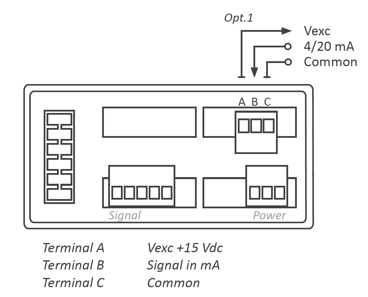
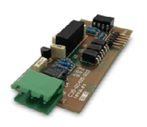
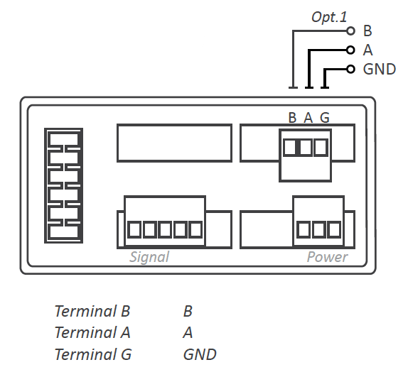
The M1 module offers 1 analog output at 4/20 mA, isolated, to be installed at slot Opt1.
The 4/20 mA output signal is fully scalable, both with positive and negative slopes, and is proportional to the reading of the instrument. The mA output can be connected to work in active loop (the module provides the power of the loop) or passive mode (the power of the loop is not provided by the instrument)
Connections
For an active 4/20 mA loop, connect terminal A (‘Vexc +15 Vdc’) as current output and terminal B (‘Signal in mA’) as return of current. For a passive 4/20 mA loop, connect terminal B (‘signal in mA’) as current output and terminal C (‘GND’) as return of current.
| Output signal | 4/20 mA (active and passive) |
| Active output | connect terminal A (+15 Vdc) and B (mA)RL<350 R |
| Passive output | connect terminal C (GND) and B (mA)RL< 700 R |
| Accuracy | <0.5% FS |
| Response time | <100 mSeg. + meter response time |
| Isolation | 1000 Vdc |
| Slots allowed | Opt.1 |
If the M1 module has been acquired installed in the instrument, then the module has been factory calibrated. In this case you can jump directly to point 7 below.
If the M1 module has been acquired separately and installation is needed, follow the next steps :

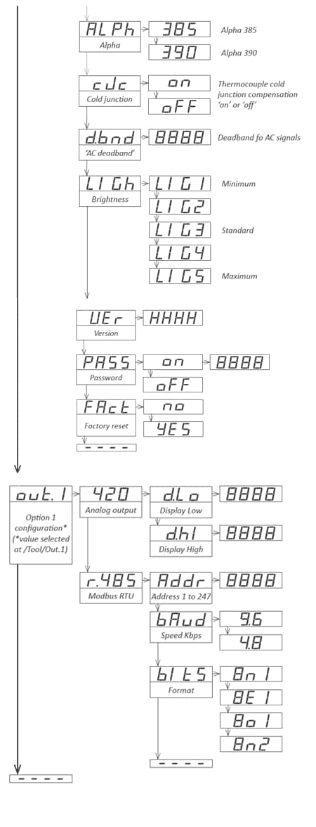
The S1 module offers 1 Modbus RTU serial output, isolated, to be installed at slot Opt1.
Configuration is done from the front keypad, through the configuration menu. The instrument must be informed that there is a Modbus RTU module at slot.1 and this is done at the configuration menu ‘Tool’ \ ‘out.1’ (see section 1.29.7). Then configure the bus parameters at the configuration menu ‘out.1’ \ ‘r485’ (see section 1.29.8).
The S1 module can be ordered installed in to a Series C instrument or standalone for later installation, as it does not require soldering or special configuration.
| Protocol | Modbus RTU | |
| Bus type | RS-485, configurable for 9.600 or 4800 bps | |
| Addresses | 1 to 247 | |
| Formats | configurable 8n1, 8e1, 8o1, 8n2 | |
| Function code | 4 | read register |
| Registers | 0 | reading value (16 bits) |
| 1 | number of decimals (16 bits) | |
| Errors | 0 | function not supported |
| 1 | register not accessible | |
| Isolation | 1000 Vdc | |
| Slots allowed | Opt.1 |
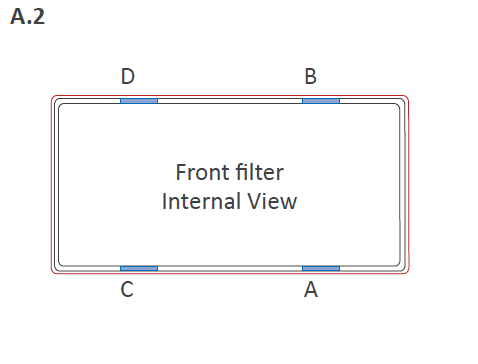
Locate the 4 clips (A B C D). Clips are covered by the front filter.
Clips can be seen when looking from the rear of the instrument, just below the front filter.

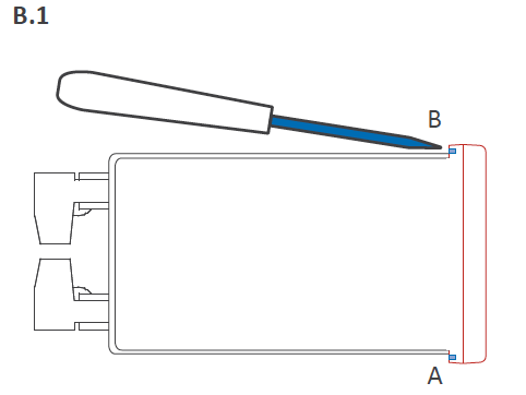
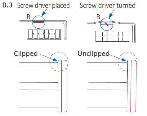
Place a flat screw driver at the first clip. Insert firmly until the end of the clip space, and then turn gently the screwdriver clockwise approx. 45º (while still pushing against the clip). The front filter will ‘move up’ and unclip itself. Clip is unclipped when the front filter corner moves slightly to the front.
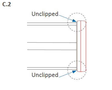
Repeat for remaining 3 clips. All 4 clips are now unclipped.
Front filter is slightly moved to the front on each corner. It can now be removed by hand.
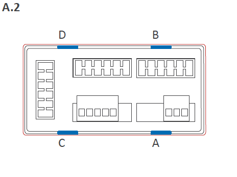
A. Locate the clips
Locate the 4 clips (A B C D) at the housing (image A.1) and the 4 matting clips at the filter (image A.2). With the instrument inside the housing, face the front filter against the housing (do not clip yet). Do not press the rear terminals with your hand, as the instrument would force the filter outwards.
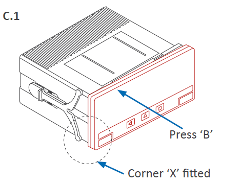
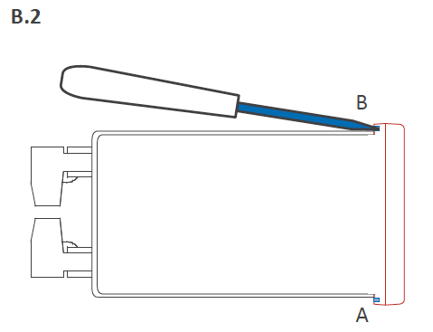
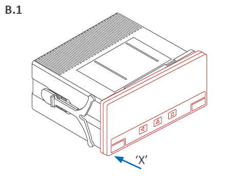
B. Fit corner 'X' and clip 'A'
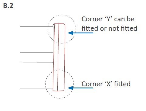
Fully insert corner 'X' into the housing. See at image B.2 that the filter is not yet clipped : only corner 'X' is completely fitted. Corner 'Y' can be also fitted or not fitted (it is not important). With corner X fitted and firmly pressed (it must remain fitted), press clip ‘A’ and it will clip (you will hear a clear 'snap').
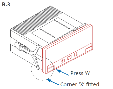
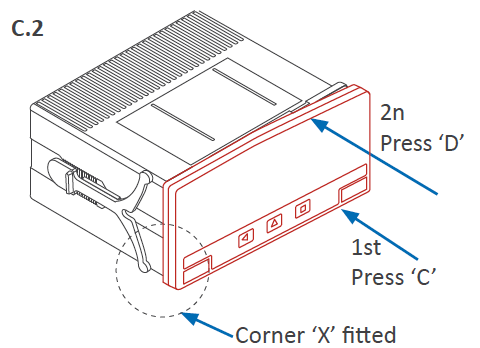
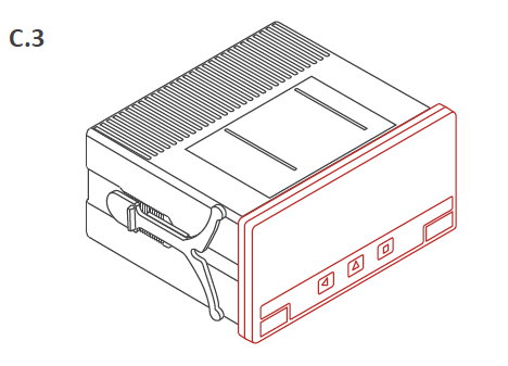
C. Clip remaining clips 'B’, 'C' & 'D'
Still press firmly corner 'X' until all four clips are clipped. You can release your finger from clip 'A' as clip ‘A’ will not unclip once it is clipped. Press on clip 'B' until it clips (you will hear a clear ‘snap’). Then press on clips 'C' and 'D' (you will hear a clear ‘snap’ on each case).