While there is almost no limitation to the impact computers can have on the practice of data acquisition, they do have certain limitations. For one, computers speak only a binary language of ones and zeros. Manufacturing processes and natural phenomena, however, are, by their very nature, analog.
In many industrial applications, there is a necessity for analog measurements – such as pressure, temperature, flow rate, load, ph/conductivity, and position – to be meaningfully recorded or manipulated by a computer. Inherently digital events, too – such as the tripping of a motor or a pulse generated by a positive displacement flowmeter – must be made interpretable as a transistor-to-transistor logic (TTL) level changes in voltage. In order for a data acquisition device to work effectively and accurately, the signal output from these various sensors requires signal conditioning.
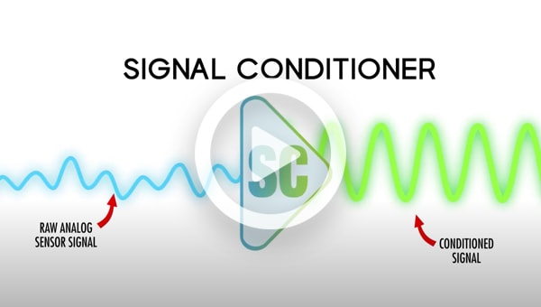
Signal conditioning, a vital process performed within a data acquisition system, involves the manipulation of the analog signal output from sensors in preparation for the next stage of processing. Signal conditioning amplifies and converts signals from various sensors and transducers into easy-to-read, compatible forms for data acquisition systems.
This process of ‘conditioning’ signals is performed through an instrument called a signal conditioner – a device that converts one type of signal into a signal that is compatible with process monitoring and control devices.
Why is Signal Conditioning Important?
In real-world applications, sensors and transducers attached to the systems for measurements are often exposed to hostile environments where faults are likely to occur. In addition, the full-scale outputs of most sensors are relatively weak. The output usually consists of small voltages, currents, or resistance changes. If the data acquisition system is fed weak signals, the output is more likely to be meaningless. Signal conditioners provide the essential circuitry between the sensor and the data acquisition system. This circuit ensures proper conditioning of the output before any further signal processing can occur. For each specific sensor, a signal conditioner serves as an interface to excite, scale, or buffer real-world signals.
How Does a Signal Conditioner Work?
A signal conditioner is a circuit that performs a set of operations on a signal and makes it suitable for further processing. It consists of an input and an output – where the input is, usually, a sensor that measures the environmental and/or structural variable.
The following are common signal conditioning types:
Amplification: Amplification is when the overall magnitude of a signal is increased – thus increasing the measurement resolution as well as the sensitivity of the signal. Strategically placed external signal conditioners can magnify the voltage level before it can be affected by environmental noise. Converting a 0-10mV signal to a 0-10V signal is an example of amplification. Thermocouples and strain gauges are sensors that typically require amplification.
Isolation: Input signals outside the range of a digitizer can cause serious damage to sensitive equipment. Isolation breaks the galvanic path between the input and output signal. By breaking the galvanic path, unwanted signals on the input line are prevented from passing through to the output. The isolator can also filter out any unwanted noise in the signal path – and eliminate any electrostatic interference caused by ground loops, which can also damage any devices that are connected to the sensor. The input is normally transferred to the output by converting it to an optical or magnetic signal then it is reconstructed on the output. Isolation is also used to prevent ground loops. If a sensor is on a different ground plane from the measurement sensor, such as a thermocouple mounted on an engine, isolation may also be needed.
Linearization: Linearization is the action of converting a non-linear input signal to a linear output signal – and is necessary when sensors produce signals that are not linearly related to the physical measurement. A thermocouple is an example of a sensor that requires linearization.
Filtering: Not all of the signal frequency spectrum contains valid data. In fact, some frequencies – like those found in a 50-60 Hrz AC power lines – can cause unwanted noise in the signal. This is where filtering is used to eliminate those unwanted frequencies for a clean and consistent signal.
Excitation: Excitation voltage is required for the operation of an active sensor such as a thermistor, an RTD, or a pressure sensor. The stability and accuracy of the excitation signal directly affects the stability and accuracy of the sensor.
Cold-Junction Compensation: Cold-junction Compensation (CJC) is used for thermocouples – and is required to ensure accurate measurements. CJC adjusts the thermocouple signal for fluctuations in room temperature and improves measurement accuracy.
Signal Conditioners
Signal conditioning is an essential aspect of any data acquisition system and there are many different types of signal conditioners – differing based on both the physical value that they measure as well as according to specific features.
Omega offers a variety of signal conditioner options.
Specialty Conditioners

Specialty signal conditioners are devices used in industrial and laboratory settings to modify and improve the quality of signal inputs before they are processed or analyzed. They often serve specific functions, such as:
- Signal conditioning, obviously. They modify signals to make them more suitable for processing. This can involve amplifying, filtering, or isolating the signal.
- Calibration: They help ensure that sensors and instruments provide accurate readings by compensating for drift or other inaccuracies.
- Conversion: They can convert signals from one format to another, such as from analog to digital.
- Protection: Specialty signal conditioners can protect sensitive instruments from voltage spikes or electrical noise.
- Isolation: They can isolate a signal to prevent ground loops or interference from other equipment.
DIN Rail Signal Conditioners

DIN Rail Signal Conditioners are crucial for precise data recording across various industrial, commercial, and laboratory settings. They transform input signals from multiple sources into a standardized output, enabling accurate measurement from devices such as thermocouples, strain gauges, RTDs, load cells, and others.
Head Mount Signal Conditioners

Head Mount Signal Conditioners are utilized in numerous industrial, commercial, and laboratory applications. They are specifically designed to convert and condition electrical signals from various sensors, including thermocouples, RTDs, ohms, potentiometers, and millivolt signals.
Omega Engineering provides a diverse selection of Head Mount Signal Conditioners that can be easily configured and scaled to meet specific requirements. Our conditioners come equipped with a range of user-friendly features, such as pushbutton configuration, LED displays, SSR outputs, and user trimming options. Compact in size, they are available in multiple input and transmission configurations.
Universal Programmable Transmitters

Universal Programmable Transmitters (UPTs) are extensively used across industrial, commercial, and laboratory settings. They provide an efficient and precise means to monitor and control processes. UPTs offer isolated inputs and outputs and can be programmed to measure or output a variety of process signals.
Omega Engineering presents a broad selection of UPTs that are UL and c-UL approved, ensuring high accuracy. These transmitters are user-friendly, easy to install, and feature a local user interface with front panel buttons for control and monitoring. They serve as an effective solution for industries and labs needing accurate measurement and control of process signals.
Temperature and Humidity Transmitters

Temperature and humidity transmitters play a vital role in various industrial, commercial, and laboratory applications. Omega Engineering provides a diverse range of these transmitters, enabling both remote and on-site monitoring of temperature and relative humidity.
Our Temperature and Humidity Transmitters are engineered for precise measurement and monitoring in different industrial and laboratory environments. With options like remote probes, stainless-steel housing, and wall or duct-mounted models, our transmitters are built for reliability and accuracy.

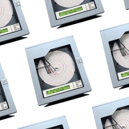
Chart Recorders Introduction to Chart Recorders