Skip to search Skip to main content Skip to navigation

Call us at 1-888-826-6342
We noticed you are from . Visit your local site for regional offers and live support.

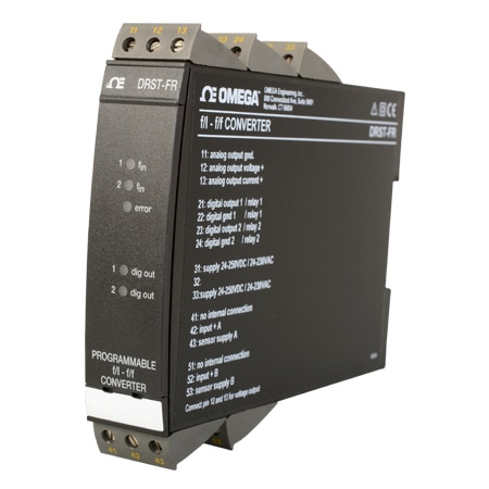
DIN Rail Frequency Input Signal Conditioner | Configurable

Programmable Signal Converter for Frequency
Warranty
  • RoHS Icon
  • CE Approved

$520.28

Item# DRST-FR

Volume discounts available
Volume Discount Schedule
Quantity Price each
1-4 $520.28
5-9 $494.27
10-24 $483.86
25-49 $463.05
50-99 $452.64
100+ $442.24

In stock

Lead Time (If not in stock): 18 weeks
Programmable Signal Converter for Frequency DRST-FR DRST-FR
  • Configurable with a standard PC and TXUN-KIT communications unit
  • Pulse Calculator
  • Frequency Generator
  • Galvanic Isolation

DRST-FR Model Options

View all models

Edit these specs to order a different model. Not all combinations are valid. Options compatible with previous selections will be in bold.

*Highlighted options are not compatible. Please select a different combination.

Input Type
Input Class
Input Ranges
Output Type
Output Class
Display Type
Supply Voltage Type
Isolation
Programability
Additional Feature


Advanced Features
• The DRST-FR signal converter can be configured with OMSET software in a standard PC and the TXUN-KIT communications unit.
Application
• The f/I function performs frequency to current and voltage conversion.
• The f/f function can be used for pulse division or multiplication and as a buffer collecting fast pulse trains.
• A scale factor may be entered in all functions. Using both digital inputs, pulse addition or subtraction are possible.
• The frequency generator function is used as e.g. a time base or clock generator.
• Input and supply polarity reversal protection. Current and voltage output signals galvanically separated from the supply and the inputs.
• Programmable digital outputs including NPN, PNP or relay options.
Technical Characteristics
• 5 front LEDs, indicating f1 and f2 active inputs (not NPN), Dig.out.1 and 2 active outputs, and a programmable error signal.
• Analog current output can be configured to any current within 0 to 20 mA range.
• Voltage output range is selectable between 0 to 10 Vdc and 0 to 1 Vdc by use of internal jumpers.
• Input range: Frequency: 0 to 20,000 Hz Sensor types: NAMUR, tacho, NPN, PNP, TTL, S0
• Output range: Current and voltage output: 0 to 20 mA / 0...10 V Relay outputs: 0 to 20 Hz NPN and PNP output as f/f: 0 to 1000 Hz NPN and PNP output as generator: 0 to 20,000 Hz

Specifications
Environmental Conditions
Operating Temperature: -20 to 60°C
Calibration Temperature: 20 to 28°C
Relative Humidity: < 95% RH (non-cond.)
Protection Degree: IP20
Mechanical Specifications
Dimensions (HxWxD): 109 x 23.5 x 130 mm
Weight Approx: 240 g
DIN Rail Type: DIN 46277
Wire Size: 1 x 2.5 mm2 stranded wire
Screw Terminal Torque: 0.5 Nm
Common Specifications
Supply
Supply Voltage, Universal:21.6 to 253 Vac, 50 to 60 Hz or 19.2 to 300 Vdc
Fuse: 400 mA SB / 250 Vac
Max. Required Power: 3.5 W
Internal Power Dissipation:3 W
Isolation Voltage
Isolation Voltage, Test/Working: 3.75 kVac / 250 Vac
Power-Up Delay: 0 to 999 s
Warm-Up Time:1 min.
Programming: Loop Link
Signal/Noise Ratio: Min. 60 dB
Response Time, Analog:< 60 ms + period
Response Time, Digital Output: < 50 ms + period
Signal Dynamics, Output:16 bit
Effect of Supply Voltage Change: < 0.005% of span/Vdc
Auxiliary Voltage: NAMUR Supply: 8.3 Vdc ±0.5 Vdc / 8 mA
S0 Supply: 17 Vdc/20 mA
NPN/PNP Supply: 17 Vdc/20 mA
Special Supply (Programmable): 5 to 17 Vdc/20 mA
Temperature Coefficient:< ±0.01% of span/°C
Linearity Error: < 0.1% of span
EMC Immunity Influence: < ±0.5%
Input Specifications
Common Input Specifications
Max. Offset: 90% of selected max. frequency
Measurement Range: 0 to 20 kHz
Min. Measurement Range: 0.001 Hz
Max. Frequency, with Input Filter ON: 50 Hz
Min. Period Time with Input Filter ON: 20 ms
Input Types: NAMUR acc. to DIN 19234
Input Types:Tacho
Input Types:NPN/PNP
Input Types:2-phase encoder
Input Types:TTL
Input Types:S0 acc. to DIN 43864
Output Specifications
Common Output Specifications
Updating Time: 20 ms
Current Output
Signal Range: 0 to 20 mA
Min. Signal Range: 5 mA
Load (@ Current Output): ≤ 600 Ω
Load Stability: ≤ 0.01% of span/100 Ω
Current Limit: < 23 mA
Voltage Output
Signal Range: 0 to 10 Vdc
Min. Signal Range: 250 mV
Load (@ Voltage Output): ≥ 500 kΩ
Relay Output
Max. Switching Frequency: 20 Hz
Max. Voltage: 250 VRMS
Max. Current: 2 AAC
Max. AC Power: 100 VA
Max. Load at 24 Vdc:1 A
Other Output Types: Active outputs (NPN/PNP)
Other Output Types: f/f Converter Output
Other Output Types: Frequency generator
Of Span: = of the presently selected range
Observed Authority Requirements
EMC: 2014/30/EU
LVD: 2014/35/EU
EAC: TR-CU 020/2011
loading all models
loading all reviews
Rated 5 out of 5 by from Valuable Programmable Signal Converter This product fits our use since it is stable and easy to use.
Date published: 2023-02-28
  • y_2024, m_3, d_27, h_9
  • bvseo_bulk, prod_bvrr, vn_bulk_3.0.38
  • cp_1, bvpage1
  • co_hasreviews, tv_0, tr_1
  • loc_en_US, sid_DRST-FR, prod, sort_[SortEntry(order=HELPFULNESS, direction=DESCENDING), SortEntry(order=POSITIVE_FEEDBACK, direction=DESCENDING), SortEntry(order=SUBMISSION_TIME, direction=DESCENDING)]
  • clientName_omega
  • bvseo_sdk, java_sdk, bvseo-4.0.0
  • CLOUD, getReviews, 6ms
  • REVIEWS, PRODUCT
loading all QA

Is the TXUN-KIT require for setup?

Asked by: PHoov
Thank you for your question. The max input voltage from a tach is 80 VAC pp
Answered by: Application Engineer PV
Date published: 2023-11-17

Hi, What is the maximum Input Voltage signal ( From Tacho) it can handle? Thanks.

Asked by: Sigi
Thank you for your question. Max. input voltage......................... 80 VAC pp
Answered by: Application Engineer PV
Date published: 2023-12-11

is it possible to take one input signal and condition it into two outputs simultaneously? for example a analog output scaled from 0-5VDC and a conditioned square wave of 10Vpp that matches the input frequency? thank you in advance

Asked by: joel
Hello Joel I'm sorry it does not have that capability, though what you can do is connect the output of the device to a DRSL-SP2 signal splitter and it can split it to two output signals.
Answered by: JA Engineer
Date published: 2020-04-03
  • y_2024, m_3, d_27, h_9CST
  • bvseo_bulk, prod_bvqa, vn_bulk_3.0.38
  • cp_1, bvpage1
  • co_hasquestionsanswers, tq_3
  • loc_en_US, sid_DRST-FR, prod, sort_[SortEntry(order=NUM_ANSWERS, direction=DESCENDING)]
  • clientName_omega
  • bvseo_sdk, java_sdk, bvseo-4.0.0
  • CLOUD, getContent, 22ms
  • QUESTIONS, PRODUCT
en-US
en
Save Configuration